Home / Door Hardware
Installation Instructions for Detex 03R Advantex Trim
A comprehensive installation guide for the Detex 03R Advantex Trim for narrow stile CVR applications. This manual covers door preparation, cylinder assembly, and mounting procedures.
Table of contents
Manual images
Click an image to enlargeQuick guide from the manual
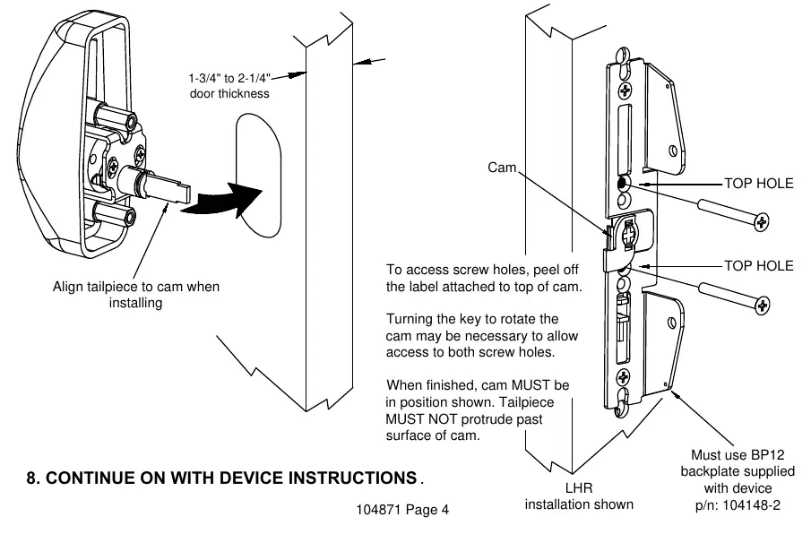
This document provides installation instructions for the Detex 03R Advantex Trim. Important: The trim must be installed before the exit device is assembled to the door. Ensure you have the required BP12 backplate (supplied with the exit device) before beginning. The unit is designed for doors 1-3/4 to 2-1/4 inches thick. For 2-1/4 inch thick doors, you must use the longer tailpiece (p/n 105239-1) provided.
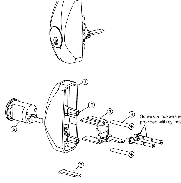
Parts breakdown
The trim assembly consists of the trim housing, hex standoffs, trim tailpiece assembly, and mounting screws. Ensure all parts listed in the parts breakdown are present before starting installation. The cylinder (5 pin or 7 pin) is sold separately.
Door preparation
Device side: Prepare the door according to the instructions provided with the exit device. Use a pencil, center punch, and power drill to prepare the necessary holes.
Transferring centerlines: Transfer the device vertical and horizontal centerlines from the device side to the trim side of the door. Use a square to ensure accuracy and account for the door bevel.
Trim side: Prepare the hole and slotted opening on the trim side of the door using the provided template (p/n 105285).
Cylinder preparation
Cut the rim cylinder tailpiece to the appropriate length as shown in the diagram. Ensure the break-away cylinder screws are cut to the proper length for your door thickness.
Trim assembly and installation
- Assemble the cylinder (with key removed), trim housing, and tailpiece assembly.
- If the door is 2-1/4 inches thick, replace the default tailpiece with the longer one (p/n 105239-1).
- Secure the BP12 backplate to the door.
- Align the tailpiece to the cam on the backplate.
- Install the trim using the appropriate length screws in the top holes above and below the cam.
- If necessary, peel off the label on top of the cam to access screw holes. You may need to turn the key to rotate the cam for access.
- Ensure the cam is in the correct position when finished and the tailpiece does not protrude past the surface of the cam.
Technical support
If you encounter issues, contact Detex Technical Support at 1-800-729-3839 (choose option 2). Do not return the product to the distributor.
Manufacturer information
Detex Corporation
Practical help
Common problems
Trim does not fit door thickness
Use the provided longer tailpiece (p/n 105239-1) for 2-1/4 inch thick doors.
Cannot access screw holes during installation
Peel off the label attached to the top of the cam. Use the key to rotate the cam if necessary to clear the screw holes.
Trim not installing correctly
Ensure the BP12 backplate is secured first. The trim must be installed before the exit device is assembled to the door.
Before use
- Verify door thickness (1-3/4 to 2-1/4 inches).
- Ensure BP12 backplate is available (supplied with exit device).
- Wear safety glasses.
- Gather tools: Pencil, Center Punch, Hammer, Power Drill, 1-1/4 inch Hole Saw, Drill Bit & Tap Set, Phillips Screwdriver, Tape Measure.
Specs in practice
- 1-3/4 inch door
- Standard thickness, uses default tailpiece.
- 2-1/4 inch door
- Requires longer tailpiece (p/n 105239-1).
Images and diagrams
- Parts Breakdown: Shows the assembly order of the trim housing, standoff, tailpiece, and screws.
- Door Prep: Illustrates how to transfer centerlines from the device side to the trim side.
- Installation: Shows alignment of the tailpiece to the cam and screw placement.
Model compatibility
- Compatible with 60, F60, 61, F61, 62, F62, 63, F63 Series.
- Requires BP12 backplate (supplied with exit device).

Manual page author
David Miller
Documentation analyst
Organizes user manual content into clear summaries, with attention to model details, product context, and everyday usability.