Home Appliances / Washing Machines
Digitech 12V Programmable Interval Timer Module Instruction Manual
Quick guide for the Digitech 12V Programmable Interval Timer Module (AA-0378). Includes jumper configuration, wiring diagrams, and technical specifications for setup.
Table of contents
Manual images
Jump to the sectionQuick guide from the manual
This document provides instructions for the Digitech 12V Programmable Interval Timer Module (AA-0378). The module is designed for precise timing control using jumper-based configuration. Users must ensure the module is kept dry and never attempt to modify or repair the internal circuitry.
Installation and Wiring
To connect the device, follow the circuit diagram provided in the manual:
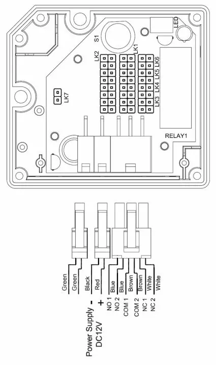
- Power Supply: Connect the red and black cables to a 12V DC power source.
- Switching: Connect the device to be controlled to the NO (Normally Open) and COM terminals for normally open function, or the NC (Normally Closed) and COM terminals for normally closed function.
- Reset: Press the reset button to restart the selected timer function.
Jumper Settings
The timer's behavior is determined by the position of jumpers on the board:
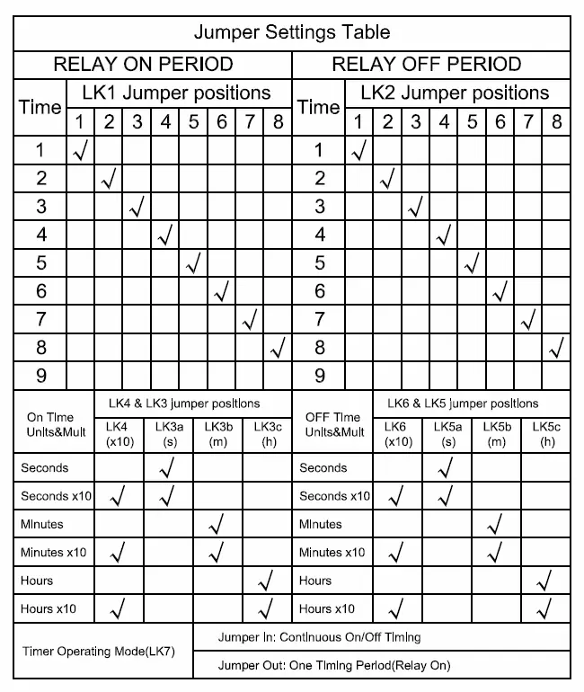
- Relay ON/OFF Period: Use the LK1 (ON) and LK2 (OFF) jumper positions to set the duration (1-9).
- Units and Multipliers: Use LK3/LK4 for ON time units (seconds, minutes, hours) and LK5/LK6 for OFF time units.
- Operating Mode (LK7): Insert the jumper for continuous ON/OFF cycling; remove the jumper for a single timing period (Relay ON).
Technical Specifications
- Power Input: 12V DC
- Current Drain: Less than 50mA when relay is ON, less than 5mA when relay is OFF
- Timing Accuracy: ±1% at all settings
- Dimensions: 72(L) x 65(W) x 43(H) mm
Practical help
Common problems
Timer not cycling continuously
Ensure the LK7 jumper is inserted for continuous ON/OFF timing mode.
Device not switching as expected
Verify wiring connections: use NO/COM for normally open or NC/COM for normally closed functions.
Before use
- Ensure the power supply is exactly 12V DC.
- Check that the module is kept in a dry environment.
- Configure jumpers according to the desired timing period before applying power.
- Confirm the load device is compatible with the relay configuration.
Specs in practice
- Timing Accuracy ±1%
- The timer will operate within a 1% margin of error for all selected settings.
Images and diagrams
- The circuit diagram shows the color-coded wiring for power (Red/Black) and relay outputs (Blue/Brown/White).
- The jumper settings table maps specific time values (1-9) and units (seconds/minutes/hours) to the physical jumper pins on the board.
Model compatibility
- The module is strictly for 12V DC systems.
- Do not exceed the relay's switching capacity.

Manual page author
Michael Turner
Technical manual editor
Reviews PDF manuals for structure, safety notes, and practical product details so readers can find the right information quickly.