HVAC / Heat Pumps
Installation and Operating Instructions for Dimplex LA 0712BW Heat Pump
A comprehensive installation and operating guide for the Dimplex LA 0712BW and LA 0712BWC air-to-water heat pumps. This manual covers safety, transport, installation, electrical connections, commissioning, maintenance, and technical...
Table of contents
Manual images
Click an image to enlargeQuick guide from the manual
This document provides essential instructions for the installation and operation of the Dimplex LA 0712BW and LA 0712BWC air-to-water heat pumps. Key requirements include:
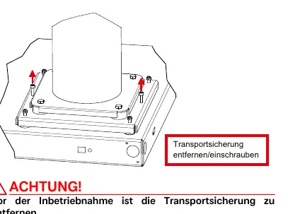
- Transport: The unit must not be tilted by more than 45° in any direction. Transport bolts must be removed before commissioning.
- Installation: The unit must be installed on a permanently smooth, even, and horizontal surface. Maintain specific clearances to walls (0.5m, 2.0m, 0.4m) to ensure proper airflow and maintenance access.
- Condensate: The condensate pipe must have a minimum diameter of 50mm and be installed frost-free.
- Commissioning: Must be performed by an authorized service technician. A minimum return temperature of 18°C is required for operation.
Safety notes
The heat pump is designed for domestic use. It can be used by children aged 8 and over under supervision. CAUTION! Immediate danger to life or severe property damage can occur if safety instructions are ignored. Always ensure the unit is disconnected from the power supply before opening the casing, and wait at least 5 minutes for electrical charges to dissipate.
Operating principle
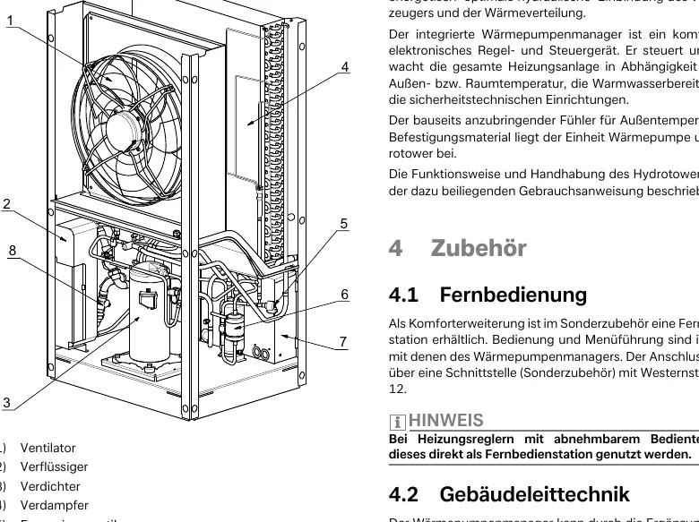
The heat pump extracts heat from the surrounding air via an evaporator and transfers it to the heating water using a compressor. In cooling mode (device-dependent), the process is reversed. The system is not suitable for operation with a frequency converter.
Transport
Transport the unit using a pallet, lift truck, or hand truck. Remove the four transport bolts connecting the unit to the pallet. Ensure no components are damaged when inserting pipes through the frame.
Installation
The heat pump should be set up so the air outlet is perpendicular to the main wind direction. Installation in hollows or inner courtyards is prohibited as cooled air may be re-circulated. The unit is not intended for use above 2000 meters above sea level.
Assembly
Heating connection
Flush the heating system thoroughly before connecting the heat pump to remove impurities. Use a spanner to grip transitions when connecting. The system must be filled, purged, and pressure-tested after installation. Use pre-filtered water (max. 5 µm pore size) for filling.
Electrical connection
Three lines are required: power supply (5-core cable), control voltage (via heat pump manager), and a shielded communication line (J-Y(ST)Y ..LG). Ensure a clockwise rotating field for the power supply; incorrect wiring will prevent the unit from starting.
Commissioning
Commissioning is performed via the heat pump manager. If heating water temperatures are below 7°C, the water in the buffer tank must be heated to at least 18°C using a second heat generator before starting. Follow the specific startup program in the manager's menu.
Cleaning and maintenance
Do not use abrasive, acidic, or chloride-based cleaners. Clean the air side (evaporator, fan, condensate drain) of leaves and debris before each heating season. For the heating side, use a corrosion protection system if necessary. If the liquefier performance drops due to contamination, have it cleaned by a professional using 5% phosphoric or formic acid.
Troubleshooting
Faults are indicated on the heat pump manager display. Consult the "Faults and troubleshooting" section in the heat pump manager's operating instructions. If the fault persists, contact an authorized service technician.
Decommissioning and disposal
The unit must be disconnected from power and valves closed. Dismantling must be performed by trained personnel, ensuring proper disposal of refrigerants and oils according to environmental regulations.
Manufacturer information
Dimplex
Practical help
Common problems
Heat pump blocked
Ensure the minimum heating water flow rate is maintained in all operating states.
Heat pump will not start
Check for a clockwise rotating field in the electrical supply. An error will be displayed on the heat pump manager.
Fault indicated on display
Consult the 'Faults and troubleshooting' section in the heat pump manager's operating instructions or contact an authorized service technician.
Before use
- Ensure all connections are installed as described in Chapter 7.
- Verify all valves in the heating circuit are open.
- Ensure air intake and outlet paths are clear.
- Check that the fan turns in the direction indicated by the arrow.
- Ensure the condensate drain is functional.
- Verify settings in the heat pump manager are adapted to the heating system.
Images and diagrams
- Clearance diagram (page 8/26) shows required distances to walls (0.5m, 2.0m, 0.4m).
- Transport diagram (page 7/25) shows how to remove transport bolts.
- Hydraulic integration diagrams (page A-VII/A-VIII) show mono-energetic system setups.
Model compatibility
- Not suitable for operation with a frequency converter.
- Not intended for use over 2000 meters above sea level.
- Requires hydro-tower with heat pump manager for operation.

Manual page author
Michael Turner
Technical manual editor
Reviews PDF manuals for structure, safety notes, and practical product details so readers can find the right information quickly.