HVAC / Heat Pumps
Installation Guide for Dimplex LA 0712BW and LA 0712BWC Heat Pump
Quick installation guide for the Dimplex LA 0712BW and LA 0712BWC air-to-water heat pumps. Includes detailed electrical wiring diagrams, hydraulic connection schemes, and WPM Econ5S manager configuration.
Table of contents
Manual images
Click an image to enlargeQuick guide from the manual
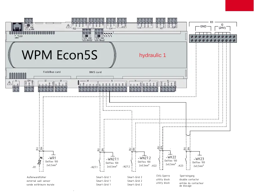
This document provides the essential electrical and hydraulic installation schematics for the Dimplex LA 0712BW and LA 0712BWC air-to-water heat pumps. It is intended for qualified installers to configure the system using the WPM Econ5S heat pump manager. The guide covers two primary hydraulic configurations and the corresponding electrical wiring requirements.
Electrical Installation
The electrical installation involves connecting the heat pump unit to the electrical distribution system and the WPM Econ5S manager. Key requirements include:
- RS485 Communication: Use a 4x0.28mm² J-Y(ST)Y cable for the RS485 bus connection between the heat pump and the manager.
- Power Supply: Ensure correct fuse protection for the heat pump (-X1), heat pump manager, and heating circuits.
- Control Inputs: Connect the utility block (EVU-Sperre) and Smart-Grid inputs as specified in the wiring diagrams.
- Cable Specifications: Use appropriate cable types (e.g., NYM-J 5x4mm², 3x1.5mm², 5x1.5mm²) based on the specific circuit load.
Hydraulic Installation
The manual outlines two distinct hydraulic configurations:
- Hydraulic 1: A standard configuration suitable for basic heat pump setups.
- Hydraulic 2: An advanced configuration supporting additional circuits, mixers, and pumps (e.g., Pump 2, Pump 3, Mixer 2, Mixer 3).
Ensure all hydraulic components, including temperature sensors (probes), are correctly positioned and connected to the WPM Econ5S controller inputs.
System Components
The system relies on the WPM Econ5S manager to control the following components:
- Sensors: External wall sensor, circuit probes (Fühler 2. Kreis, Fühler 3. Kreis).
- Actuators: Pumps (Pumpe 2. Kreis, Pumpe 3. Kreis) and Mixers (Mischer 2. Kreis, Mischer Hauptkreis/3. Kreis).
- Control Interfaces: Smart-Grid inputs and utility block contactors.
Manufacturer information
Dimplex
Practical help
Common problems
Communication error between heat pump and manager
Check the RS485 bus wiring (Tx/Rx, GND) and ensure the cable is shielded and correctly terminated.
Incorrect system operation
Verify that the hydraulic configuration (Hydraulic 1 or 2) matches the physical installation and that all sensors are connected to the correct terminals on the WPM Econ5S.
Smart-Grid or Utility Block not responding
Check the wiring of the -WK22 and -WK23 cables to the corresponding inputs on the WPM Econ5S.
Before use
- Verify that the electrical supply matches the fuse requirements (B20A, C13A, C10A).
- Ensure all cable cross-sections meet the specified requirements (e.g., 5x4mm², 3x1.5mm²).
- Confirm the hydraulic configuration (Hydraulic 1 or 2) matches the system design.
- Check all sensor connections, including the external wall sensor and circuit probes.
- Ensure the RS485 bus is correctly wired between the heat pump and the manager.
Images and diagrams
- Page 1: Main electrical wiring diagram for the heat pump and manager.
- Page 2: Hydraulic schematic for the basic system configuration (Hydraulic 1).
- Page 3: Wiring connections for the WPM Econ5S controller (Hydraulic 1).
- Page 4: Hydraulic schematic for the advanced system configuration (Hydraulic 2).
- Page 5: Wiring connections for the WPM Econ5S controller (Hydraulic 2).
Model compatibility
- Compatible with Dimplex LA 0712BW and LA 0712BWC models.
- Requires WPM Econ5S manager for operation.

Manual page author
David Miller
Documentation analyst
Organizes user manual content into clear summaries, with attention to model details, product context, and everyday usability.