HVAC / Heat Pumps
Dimplex LIA 0911HWCF M Split Water Heat Pump Installation Guide
Installation and technical reference guide for the Dimplex LIA 0911HWCF M split water heat pump. Includes detailed dimensional drawings, connection points, and installation requirements.
Table of contents
Manual images
Click an image to enlargeQuick guide from the manual
This document provides technical installation drawings and connection specifications for the Dimplex LIA 0911HWCF M split water heat pump system. It is intended for professional installers to ensure correct placement and piping connections.
Outdoor unit installation
The outdoor unit requires a stable foundation. Ensure the following clearances are maintained during installation:
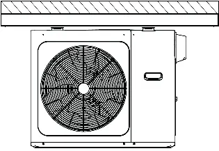
- Foundation clearance: Maintain a distance of greater than 100 units (mm) and greater than 80 units (mm) as indicated in the technical diagrams to ensure proper airflow and service access.
- Dimensions: The unit has a width of 1118 mm and a height of 865 mm.
Indoor unit connections
The indoor unit serves as the water storage and heat exchange component. Key connection points include:
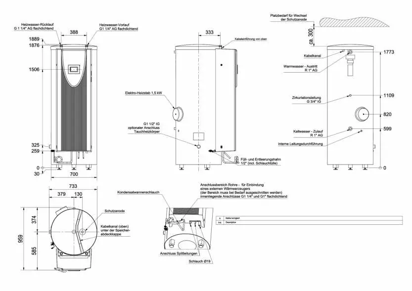
- Heating water return: G 1 1/4 inch AG (flat sealing).
- Heating water flow: G 1 1/4 inch AG (flat sealing).
- Hot water outlet: R 1 inch AG.
- Cold water inlet: R 1 inch AG.
- Circulation line: G 3/4 inch IG.
- Electric heater: Integrated 1.5 kW electric heating element.
- Sacrificial anode: Located at the top of the unit; ensure approximately 300 mm of clearance above the unit is available for future replacement.
Maintenance and service
The system includes a sacrificial anode for corrosion protection. Ensure the installation location allows for the removal and replacement of this anode. The unit also features a condensate drain hose and specific connection areas for external heat sources, which may require cutting the insulation/casing if necessary.
Manufacturer information
Dimplex
Practical help
Common problems
Insufficient clearance for sacrificial anode replacement
Ensure at least 300 mm of vertical clearance is available above the indoor unit.
Incorrect foundation placement
Follow the specified foundation dimensions (>100 mm and >80 mm) to ensure stability and proper airflow.
Before use
- Verify the foundation is level and meets the minimum clearance requirements.
- Confirm all water pipe connections (G 1 1/4, G 1, G 3/4) are prepared with appropriate fittings.
- Ensure the 1.5 kW electric heater is correctly wired.
- Check that the sacrificial anode is accessible for future maintenance.
- Verify the condensate drain hose is correctly positioned.
Specs in practice
- G 1 1/4 inch AG
- External thread size for heating water flow and return connections.
Images and diagrams
- Outdoor unit: Shows footprint, width, height, and foundation clearance requirements.
- Indoor unit: Details all water connection ports, electrical heater location, and sacrificial anode access.
Model compatibility
- The system is designed for split water heat pump configurations.
- External heat source connections are provided; ensure compatibility with the specific external unit being integrated.

Manual page author
Michael Turner
Technical manual editor
Reviews PDF manuals for structure, safety notes, and practical product details so readers can find the right information quickly.