HVAC / Heat Pumps
Installation Manual for Dimplex WPM Touch Heat Pump Manager
Professional installation and technical guide for the Dimplex WPM Touch heat pump manager. Covers mounting procedures, electrical wiring, pin assignments, sensor installation, and system configuration.
Table of contents
Manual images
Click an image to enlargeQuick guide from the manual
This document is intended for technicians installing the Dimplex WPM Touch heat pump manager. Key requirements include installation in a dry room (0-35°C) and strict adherence to electrical safety standards. Warning: Connecting line voltage to extra-low voltage terminals (adapter boards -N1/SL, -N1/ML, -N17/LV and specific pins) will destroy the device. Ensure the communication cable for outdoor heat pumps is shielded and laid separately from the mains cable.
Safety notes
Observe all country-specific safety regulations and VDE 0100 standards. The device must be operated in dry rooms without condensation. Sensor cables can be extended up to 40-50m but must not be installed next to power cables. The heat pump controller must remain connected to the power supply to ensure frost protection.
Mounting
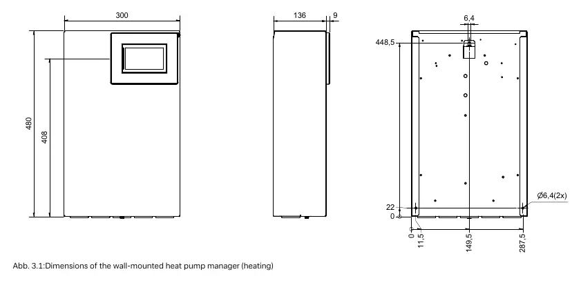
The controller is wall-mounted using the provided 3 screws and dowels.
- Open the controller cover.
- Mount the dowels for the upper fastening eyelet at operator level.
- Secure the controller, mark side drill-holes, unhook, drill, and remount.
Temperature sensor
The system uses NTC-2 and NTC-10 sensors.
- Outside sensor (R1): Mount on the north or north-west side, avoiding direct sunlight, windows, doors, or exhaust vents.
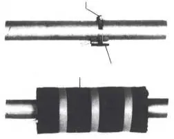
- Strap-on sensor: Clean the pipe, apply heat transfer compound, attach with a hose clip, and thermally insulate.
Electrical installation
The supply cable for the heat pump manager must have continuous voltage (L/N/PE 230V, 50Hz). The utility company blocking contactor (K22) must be dimensioned according to heat pump output. For electronically regulated circulating pumps, a coupling relay is required if starting currents are high or unknown.
Functions and pin assignment
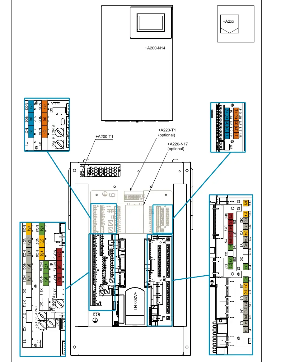
The WPM Touch features a fixed function block (grey) for general/unmixed circuits and flexible blocks (yellow, green, red, orange, blue) for additional functions like domestic hot water, mixed circuits, cooling, and solar. During commissioning via the touch display, the function and color-coded block must be assigned.
Special accessories
The system supports the RTM Econ room temperature controller for cooling regulation and can be integrated into building management systems via EIB, KNX, Ethernet, Modbus TCP, or Modbus RTU.
Technical device information
The device operates at 230V AC (195-253V range) with a power consumption of approx. < 50 VA. It has an IP 20 protection rating and is designed for an operating temperature range of 0°C to +35°C.
Manufacturer information
Dimplex
Practical help
Common problems
Device destruction
Do not connect line voltage to extra-low voltage terminals (adapter boards -N1/SL, -N1/ML, -N17/LV and pins -N1/J9..J14, J29, -N17/J6, J9).
Sensor malfunctions
Ensure strap-on sensors are tightened firmly with a hose clip and thermally insulated; loose sensors cause inaccurate readings.
High starting currents
Install a coupling relay for electronically regulated circulating pumps if the starting current exceeds the heat pump manager's permissible operating current.
Communication errors
Ensure the communication cable for outdoor heat pumps is shielded and laid separately from the mains cable.
Before use
- Verify installation environment is dry (0-35°C) and free of condensation.
- Ensure all-pole disconnecting device is installed in the power supply.
- Check that sensor cables are not installed next to power cables.
- Confirm sensor cable length does not exceed 40-50m.
- Ensure the utility company blocking contactor is dimensioned correctly.
- Verify the heat pump controller remains connected to power for frost protection.
Specs in practice
- Line voltage
- 230 V AC, 50 Hz (Range: 195 to 253 V AC).
- Degree of protection
- IP 20 (Indoor use only).
- Operating temperature
- 0°C to +35°C.
- Switching capacity
- Min. 2 A (2 A) cos (φ) = 0.6 LRA = 12 A at 230 V.
Images and diagrams
- Wall-mounted manager: Shows dimensions and mounting points for the controller.
- Strap-on sensor: Illustrates correct mounting with hose clip and thermal insulation.
- Pin assignment tables: Defines connections for fixed (grey) and flexible (colored) function blocks.
Model compatibility
- Active cooling function is only available for reversible heat pumps.
- Supports EIB, KNX, Ethernet, Modbus TCP, and Modbus RTU for building management systems.

Manual page author
Michael Turner
Technical manual editor
Reviews PDF manuals for structure, safety notes, and practical product details so readers can find the right information quickly.