HVAC / Heat Pumps
Installation Guide for Dimplex LA 0712C Heat Pump
Technical installation guide for the Dimplex LA 0712C air-water heat pump, featuring detailed electrical wiring diagrams, hydraulic layouts, and connection instructions for various system configurations.
Table of contents
Manual images
Click an image to enlargeQuick guide from the manual
This document provides the essential electrical and hydraulic connection diagrams for the Dimplex LA 0712C air-water heat pump. It is intended for qualified installers to ensure correct system integration. The guide covers two primary hydraulic configurations and the corresponding wiring requirements for the Heat Pump Manager (+A200-N1).
Electrical layout
The electrical system consists of three main components:
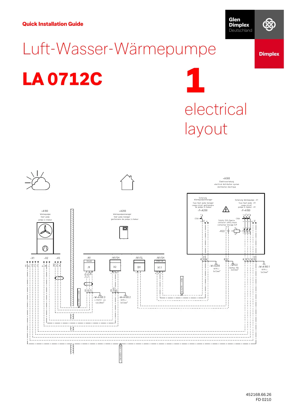
- +A100: The heat pump unit.
- +A200: The heat pump manager (controller).
- +A300: The electrical distribution system.
The wiring diagram details the connections between these units, including power supply, RS485 communication, and safety contactors (e.g., -K22 for utility block).
Hydraulic layouts
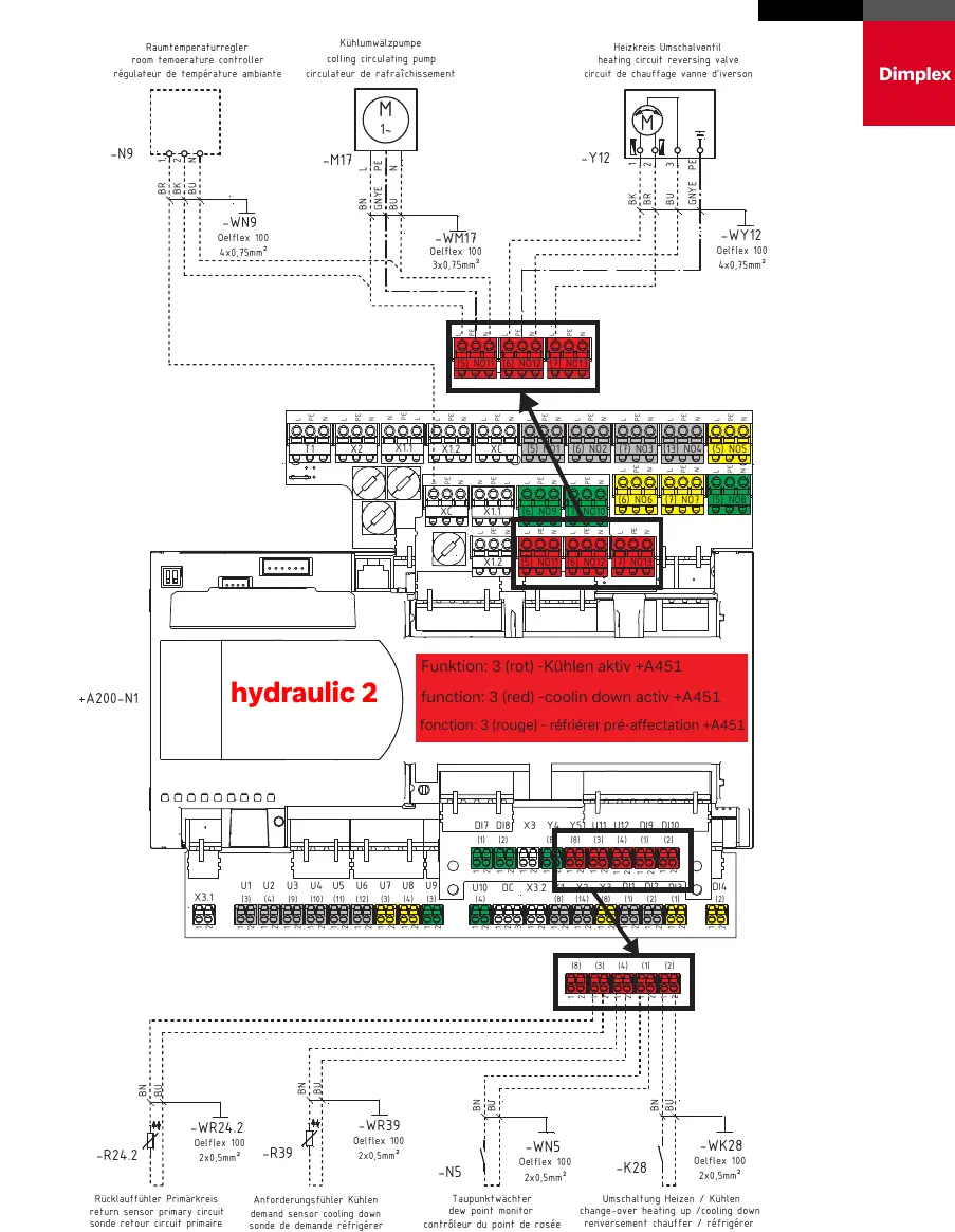
The manual provides two distinct hydraulic layouts (Hydraulic 1 and Hydraulic 2) to accommodate different system requirements. These diagrams illustrate the placement and connection of pumps, valves, and sensors, such as:
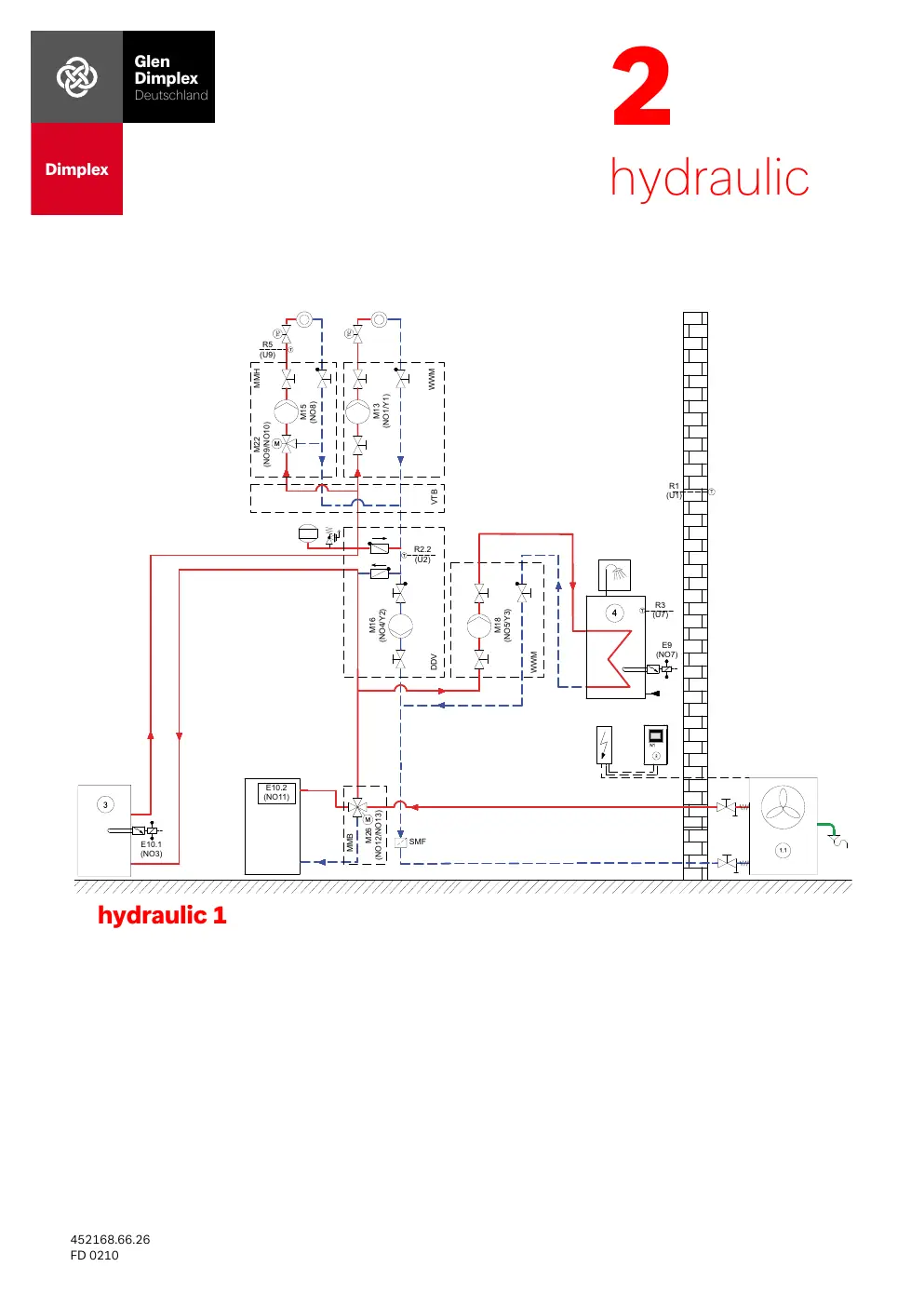
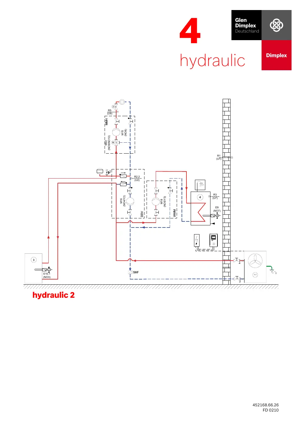
- M13/M16/M18: Circulating pumps.
- R1/R3/R5: Temperature sensors.
- E9/E10: Heating elements and bivalent sources.
Plug-in and wiring connections
The Heat Pump Manager (+A200-N1) serves as the central connection hub. The manual provides specific plug-in diagrams for different system functions:
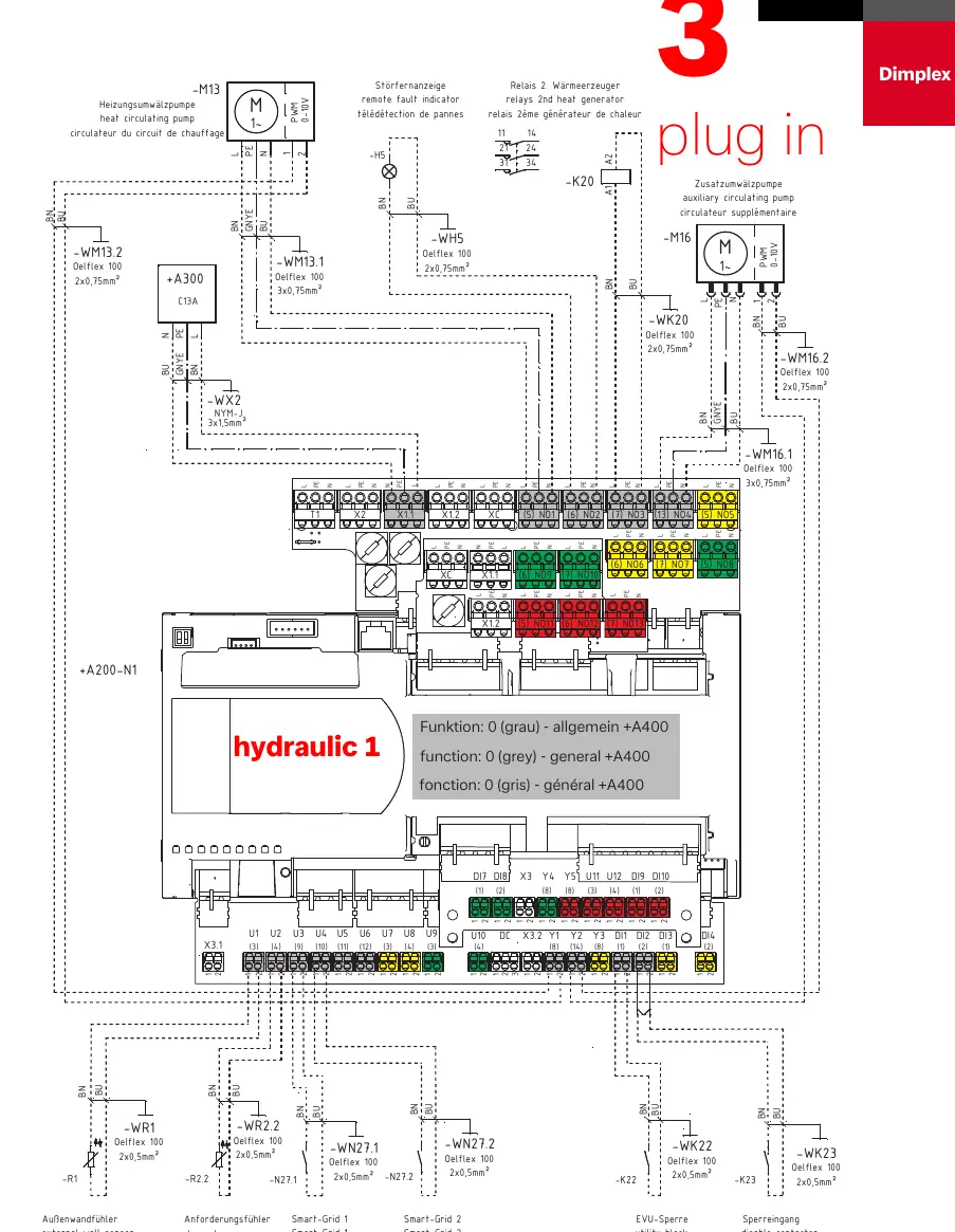
- Function 0 (General): Standard operation with basic sensors and pumps.
- Function 1 (Domestic Hot Water): Connections for hot water sensors, circulation pumps, and reversing valves.
- Function 2 (2nd Circuit): Connections for mixing valves and secondary circuit pumps.
- Function 3 (Bivalent/Cooling): Connections for bivalent heat generators or cooling system components.
Always refer to the specific plug-in diagram corresponding to your chosen hydraulic configuration (1 or 2) to ensure correct terminal assignment.
Manufacturer information
Dimplex
Practical help
Common problems
Incorrect sensor readings
Verify that sensors (e.g., -WR1, -WR2.2, -R5) are connected to the correct terminals on the +A200-N1 controller as specified in the diagram for your hydraulic configuration.
Pump not operating
Check the PWM/0-10V signal wiring and the power supply connections for the specific pump (-M13, -M16, etc.) on the controller.
Bivalent source or cooling not activating
Ensure the relay (-K20, -K21, -K28) is correctly wired to the designated NO (Normally Open) terminals and that the function configuration matches the system setup.
Before use
- Identify the required hydraulic configuration (1 or 2) for your installation.
- Ensure all electrical connections to the +A200-N1 controller are secure and match the wiring diagram.
- Verify that all sensors (temperature, demand, etc.) are connected to the correct terminals.
- Confirm the power supply matches the requirements for the heat pump and manager.
- Check that all relays and contactors are correctly wired for their intended function.
Images and diagrams
- Electrical Layout (Page 1): Shows main power and communication connections.
- Hydraulic Layouts (Pages 2 & 7): Illustrate flow and component placement for configurations 1 and 2.
- Plug-in Diagrams (Pages 3-6, 8-11): Detail specific terminal connections on the +A200-N1 controller.
Model compatibility
- Ensure the hydraulic configuration (1 or 2) is selected based on your specific system design.
- Some functions (e.g., cooling, bivalent) require specific wiring configurations as shown in the diagrams.

Manual page author
Emily Carter
User documentation editor
Prepares concise manual descriptions and highlights the most useful setup, operation, and maintenance information for readers.