HVAC / Heat Pumps
Installation and Operating Instruction for Dimplex LA 0712C Air-to-Water Heat Pump
Comprehensive installation and operating guide for the Dimplex LA 0712C air-to-water heat pump. Includes setup, electrical connection, commissioning, maintenance, and troubleshooting.
Table of contents
Manual images
Click an image to enlargeQuick guide from the manual
This document provides essential instructions for the installation, operation, and maintenance of the Dimplex LA 0712C air-to-water heat pump. Key requirements include ensuring a level installation surface, maintaining specific clearances for airflow, and verifying electrical connections (clockwise rotating field). Commissioning must be performed by an authorized technician via the heat pump manager.
Intended use
The LA 0712C is designed exclusively for heating and cooling heating water in domestic environments. It is suitable for mono-energetic and bivalent operation. Note: The device is not suitable for operation with a frequency converter.
Transport
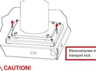
During transport, the heat pump must not be tilted by more than 45 degrees in any direction. Use a pallet for transport. Before commissioning, remove the transport locks located on both sides of the base.
Installation
The heat pump must be installed on a permanently level, smooth, and horizontal surface. Ensure the frame lies tightly against the floor for sound insulation and to prevent small animals from entering. Maintain the following minimum clearances for maintenance and airflow:
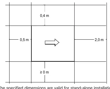
- 0.5 m and 2.0 m from sides
- 0.4 m from the rear
- 0 m minimum at the front
The air outlet direction should be perpendicular to the main wind direction to allow unrestricted defrosting.
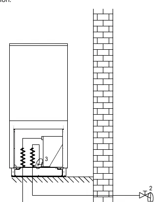
Condensate pipe
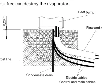
Condensed water must be drained frost-free. The condensate pipe must have a minimum diameter of 50 mm and be fed into a sewer. Do not discharge directly into clearing tanks or cess pits.
Assembly
Heating side connection
Before connecting, flush the heating system to remove impurities. Use a spanner to grip transitions. The filling water must be of drinking water quality and pre-filtered (max 5 µm). For systems with large volumes, use demineralized water and a pH stabilizer (min pH 7.5).
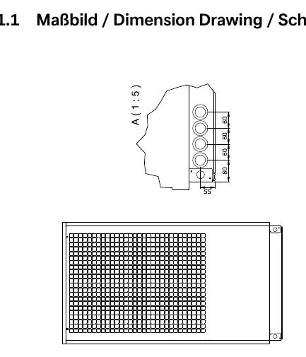
Electrical connection
Three lines/cables are required:
- Power supply: Standard 5-core cable with all-pole disconnecting device (min 3 mm contact gap).
- Control voltage: Supplied via the heat pump manager.
- Communication: Shielded line (J-Y(ST)Y ..LG) connecting the heat pump manager to the internal µPC2.
Important: Ensure a clockwise rotating field for the power supply; otherwise, the heat pump will not start.
Commissioning
Commissioning is performed via the heat pump manager. If heating water temperatures are below 7 °C, commissioning is not possible; the buffer tank must be heated to at least 18 °C using a second heat generator. Follow the program in the special functions menu of the manager.
Cleaning and maintenance
Do not use abrasive, acidic, or chloride-based cleaners. Clean the evaporator, fan, and condensate drain of debris (leaves, twigs) before each heating period. Ensure all circuits are disconnected from the power supply before opening the device. Wait at least 5 minutes after disconnecting power to allow electric charges to dissipate.
Troubleshooting
Faults are indicated on the heat pump manager display. Consult the troubleshooting section in the heat pump manager's manual. If the fault persists, contact an authorized after-sales service technician.
Manufacturer information
Dimplex
Practical help
Common problems
Heat pump blocked
Check if the minimum heating water flow rate is maintained. If it drops below the threshold, the pump is blocked.
Heat pump will not start
Verify that the electrical supply has a clockwise rotating field. Incorrect wiring prevents startup.
Performance drop
Check for contamination in the heat exchanger or air intake/outlet grids. Clean if necessary.
Ice buildup on grids
Under extreme weather, remove ice and snow from air intake and outlet grids to ensure minimum airflow.
Before use
- Remove transport locks from both sides of the base.
- Ensure all heating circuit valves are open.
- Verify air intake and outlet paths are clear.
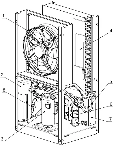
- Check that the fan rotates in the direction of the arrow.
- Ensure condensate drain is installed and frost-protected.
- Verify electrical connections (clockwise rotating field).
Images and diagrams
- Transport diagram shows lifting points and removal of transport locks.
- Installation diagram shows required clearances (0.5m, 2.0m, 0.4m) and condensate pipe routing.
- Heating connection diagram shows flow/return and drainage points.
Model compatibility
- Not suitable for operation with a frequency converter.
- Requires heat pump manager for operation.
- Compatible with Modbus, EIB, KNX, and Ethernet via interface card.

Manual page author
David Miller
Documentation analyst
Organizes user manual content into clear summaries, with attention to model details, product context, and everyday usability.