HVAC / Heat Pumps
Installation Guide for Dimplex LA 1118BW / LA 1118BWC Air-Water Heat Pump
Technical installation guide for the Dimplex LA 1118BW and LA 1118BWC air-water heat pumps. Includes detailed electrical wiring diagrams and hydraulic schematics for system integration.
Table of contents
Manual images
Click an image to enlargeQuick Installation Guide Overview
This document provides essential electrical and hydraulic installation schematics for the Dimplex LA 1118BW and LA 1118BWC air-water heat pumps. It is intended for professional installation and system integration.
Electrical Wiring
The installation requires proper connection between the heat pump (+A100), the heat pump manager (+A200), and the electrical distribution system (+A300). Key connections include:
- RS485 Communication: Uses J-Y(ST)Y 4x0.28mm² cable for data transmission between the heat pump and manager.
- Power Supply: Specific cable cross-sections are required (e.g., 5x4mm² for the manager, 3x1.5mm² for control circuits).
- Safety/Utility Block: Connections for the utility block contactor (-K22) are detailed to ensure proper grid management integration.
Hydraulic System Configurations
The guide provides two primary hydraulic configurations:
- Hydraulic 1: Standard configuration for basic heat pump operation.
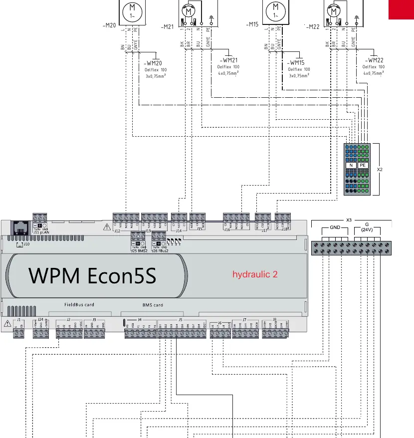
- Hydraulic 2: Advanced configuration supporting multiple circuits (Pumpe 2. Kreis, Pumpe 3. Kreis) and mixers.
Controller Connections (WPM Econ5S)
The WPM Econ5S controller manages the system. Wiring diagrams detail the connection of:
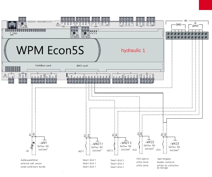
- Sensors: External wall sensor (-WR1), probe 2. circuit (-WR5), and probe 3. circuit (-WR13).
- Smart-Grid Inputs: Connections for Smart-Grid 1 and 2.
- External Control: Utility block (EVU-Sperre) and disable contactor inputs.
Manufacturer information
Dimplex
Practical help
Common problems
Communication error between heat pump and manager
Check the RS485 bus wiring (J-Y(ST)Y 4x0.28mm²) and ensure correct polarity on terminals A(+) and B(-).
System not responding to utility block signal
Verify the wiring of the EVU-Sperre contactor (-K22) to the designated input on the WPM Econ5S controller.
Before use
- Ensure the electrical distribution system matches the requirements for the heat pump and manager.
- Verify the hydraulic configuration (Hydraulic 1 or 2) matches your specific installation setup.
- Check all cable cross-sections against the provided wiring diagrams (e.g., 5x4mm², 3x1.5mm²).
- Confirm all sensors (external wall sensor, circuit probes) are correctly connected to the WPM Econ5S controller.
- Ensure the RS485 communication cable is shielded and properly grounded.
Images and diagrams
- Hydraulic 1: Basic system diagram showing the heat pump connected to the main hydraulic unit.
- Hydraulic 2: Advanced system diagram showing connections for additional heating circuits and mixers.
- WPM Econ5S Wiring: Detailed terminal-level connections for sensors, Smart-Grid, and utility inputs.
Model compatibility
- Ensure the controller firmware supports the specific hydraulic configuration (1 or 2) being installed.

Manual page author
Michael Turner
Technical manual editor
Reviews PDF manuals for structure, safety notes, and practical product details so readers can find the right information quickly.