HVAC / Heat Pumps
Installation Guide for Dimplex LA 1118CP Air-Water Heat Pump
Comprehensive installation and wiring guide for the Dimplex LA 1118CP air-water heat pump. Includes detailed electrical layouts, hydraulic diagrams, and connection instructions for sensors, pumps, and bivalent heat generators.
Table of contents
Manual images
Click an image to enlargeQuick Installation Overview
This document provides the essential electrical and hydraulic installation layouts for the Dimplex LA 1118CP air-water heat pump. It is intended for qualified technicians to ensure correct wiring of the heat pump manager, sensors, circulating pumps, and auxiliary heating systems.
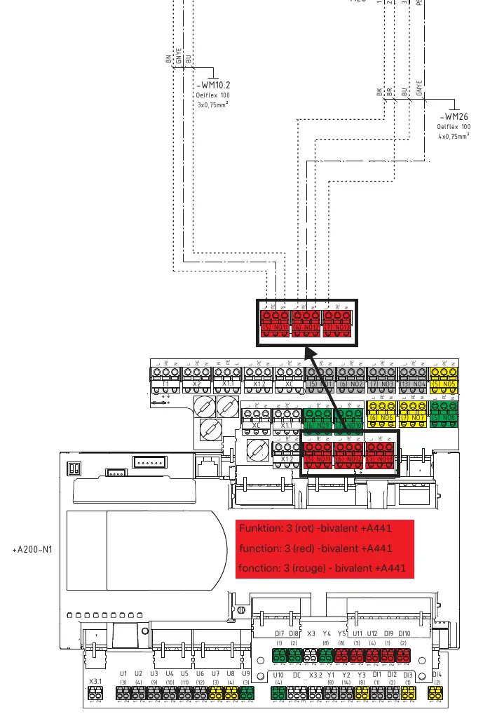
Electrical Layout
The electrical layout defines the connection between the heat pump (+A100), the heat pump manager (+A200), and the electrical distribution system (+A300). Key connections include the RS485 communication bus, power supply (230V), and the utility block (EVU-Sperre) contactor (-K22). Ensure all wiring adheres to the specified cable cross-sections (e.g., 3x1.5mm² for power, 4x0.28mm² for RS485).
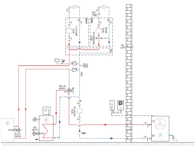
Hydraulic Layout
The hydraulic diagram illustrates the flow and component placement for the heating system. It includes the heat pump unit, circulating pumps (M13, M15, M16), mixing valves, and sensors (R1, R2.2, R3, R5). Ensure all hydraulic components are installed according to the flow direction indicated in the diagram to maintain system efficiency.
Wiring and Connections
The system utilizes a modular plug-in approach for various components. Connections are categorized by function:
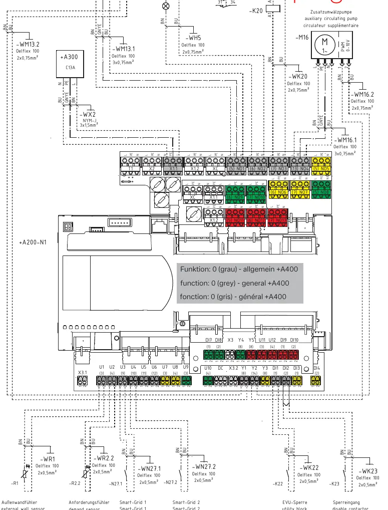
- General Connections: Includes external wall sensors (-WR1), demand sensors (-WR2.2), Smart-Grid inputs, and utility block disable contacts.
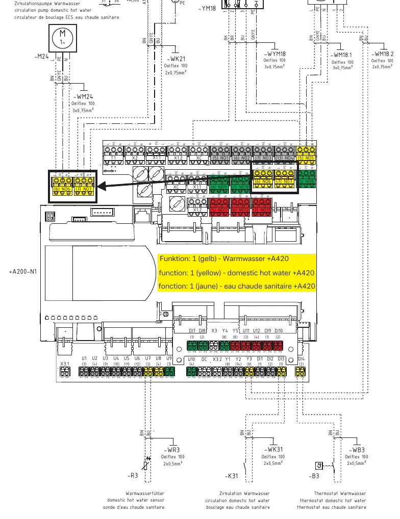
- Domestic Hot Water (DHW): Connections for the DHW pump (-M18), reversing valve (-YM18), and DHW sensor (-WR3).
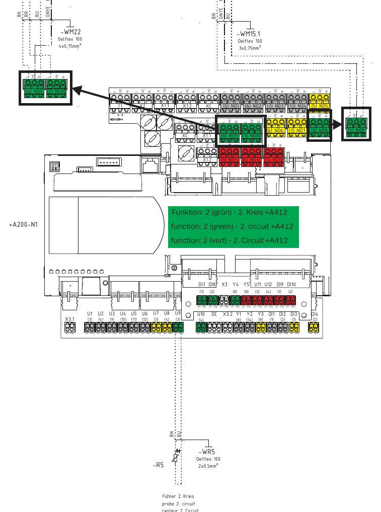
- 2nd Circuit: Connections for the 2nd circuit pump (-M15) and mixer (-M22).
- Bivalent Systems: Connections for bivalent heat generators (-E10.2) and mixers (-M26).
Always verify the terminal labels (e.g., NO1, NO2, NO3) on the heat pump manager (+A200-N1) against the specific wiring diagram for your configuration.
Manufacturer information
Dimplex
Practical help
Common problems
Communication error between heat pump and manager
Check the RS485 connection (J9) between +A100 and +A200. Ensure the 4x0.28mm² cable is securely connected and not damaged.
Circulating pump not operating
Verify the power supply (L, N, PE) and the PWM control signal wiring (0-10V) on the respective pump terminals.
Sensor reading error
Inspect the wiring for external wall sensors (-WR1) and demand sensors (-WR2.2). Ensure connections are tight and polarity is correct.
Before use
- Verify that the heat pump manager (+A200) is correctly wired to the electrical distribution system (+A300).
- Ensure all sensor cables (external wall sensor, demand sensor, DHW sensor) are connected to the correct terminals on the manager.
- Check that the utility block (EVU-Sperre) contactor (-K22) is wired according to the diagram.
- Confirm that all circulating pumps and mixers are connected to the appropriate NO (Normally Open) terminals.
- Ensure the hydraulic circuit is properly configured and free of air locks before startup.
Images and diagrams
- The diagrams use standard electrical symbols for fuses (C13A), contactors (-Kxx), and pumps (-Mxx).
- Terminals are labeled (e.g., X1, X2, NO1) to match the physical connections on the control board.
- Dashed lines indicate external wiring connections to be made during installation.
Model compatibility
- Ensure the heat pump manager configuration matches the installed hardware (e.g., bivalent vs. standard).
- Use only the specified cable types (e.g., Oelflex 100, NYM-J) as indicated in the wiring diagrams.

Manual page author
Michael Turner
Technical manual editor
Reviews PDF manuals for structure, safety notes, and practical product details so readers can find the right information quickly.