HVAC / Heat Pumps
Installation Guide for Dimplex WI 120TU Heat Pump
Quick installation and wiring guide for the Dimplex WI 120TU water-to-water heat pump. Includes electrical connection diagrams, hydraulic schematics, and WPM Econ5+ controller wiring instructions.
Table of contents
Manual images
Click an image to enlargeQuick Installation Overview
This document provides essential wiring and hydraulic connection diagrams for the Dimplex WI 120TU water-to-water heat pump. It covers the electrical distribution system, hydraulic circuit layout, and detailed wiring for the WPM Econ5+ heat pump manager.
Electrical Distribution System
The electrical connection involves the heat pump and the heat pump manager. Ensure the power supply is correctly routed through the fuses and contactors as specified in the diagram. The system utilizes NYM-J cables for main power distribution.
Hydraulic System
The hydraulic diagram outlines the flow and return paths, including connections for pumps (M11, M13, M16, M18, M21, M22) and sensors (R1, R2.1, R3, R5). Ensure all valves and pumps are installed according to the hydraulic schematic to maintain proper flow.
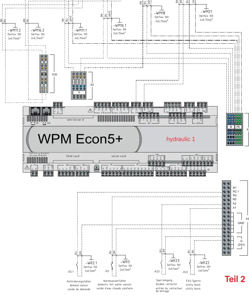
WPM Econ5+ Wiring
The WPM Econ5+ controller acts as the central management unit. Wiring connections are divided into two parts:
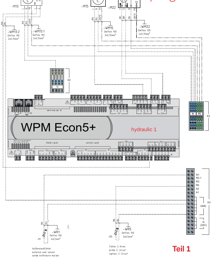
- Part 1: Connections for external wall sensors, probe 2, and various pumps (M13, M15, M22).
- Part 2: Connections for primary circuit pumps, domestic hot water pumps, and mixer circuits.
Ensure all sensor and pump cables are connected to the correct terminals on the WPM Econ5+ board as indicated in the wiring diagrams.
Manufacturer information
Dimplex
Practical help
Common problems
Incorrect pump operation
Verify that the pump (M11, M13, M16, M18, M21, M22) is connected to the correct terminal on the WPM Econ5+ controller as shown in the wiring diagrams.
Sensor reading errors
Check that the external wall sensor (R1) and probe 2 (R5) are wired to the correct X3 terminal block.
Before use
- Verify all electrical connections match the provided wiring diagrams.
- Ensure the WPM Econ5+ controller is powered with 24V AC.
- Check that all hydraulic pumps and sensors are correctly identified and connected.
- Confirm cable types (e.g., Oelflex 100, NYM-J) match the specifications for each connection.
Specs in practice
- WPM Econ5+ Input
- 24V AC, 50-60 Hz, max power 40 VA/15W.
Images and diagrams
- Page 1: Electrical distribution system diagram showing fuses and contactors.
- Page 2: Hydraulic circuit diagram showing pump and sensor locations.
- Page 3: WPM Econ5+ wiring diagram (Part 1) for pumps and sensors.
- Page 4: WPM Econ5+ wiring diagram (Part 2) for primary and hot water circuits.
Model compatibility
- Designed specifically for the Dimplex WI 120TU water-to-water heat pump system.

Manual page author
Michael Turner
Technical manual editor
Reviews PDF manuals for structure, safety notes, and practical product details so readers can find the right information quickly.