HVAC / Heat Pumps
Installation Guide for Dimplex LIA 1316HXCF Air-to-Water Heat Pump
Quick installation and wiring guide for the Dimplex LIA 1316HXCF air-to-water heat pump. Includes detailed electrical layouts, hydraulic diagrams, and connection instructions for sensors, Smart-Grid, and heating/cooling functions.
Table of contents
Manual images
Click an image to enlargeQuick guide from the manual
This document provides essential electrical and hydraulic installation instructions for the Dimplex LIA 1316HXCF air-to-water heat pump. It is intended for professional installers to ensure correct system integration between the heat pump unit, the Hydrobox, and the electrical distribution system.
Electrical layout
The electrical installation requires connecting the heat pump (+A100) to the Hydrobox (+A200) and the electrical distribution system (+A300). Key components include:
- FBUS 1 (J9): Communication bus connection between the heat pump and the Hydrobox using J-Y(ST)Y 4x0.28mm² cable.
- Power Supply: Ensure correct fusing for the Hydrobox, heat pump manager, and the heat pump itself (-X1).
- Safety: Proper grounding (PE) and neutral (N) connections are critical for all components.
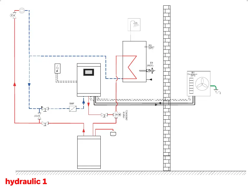
Hydraulic system
The hydraulic diagram outlines the flow and component placement for the system. Ensure all valves, sensors, and pumps are installed according to the schematic to maintain proper circulation and heat exchange efficiency.
Plug-in connections
The system supports various functions via terminal connections on the Hydrobox (+A200-N1). Wiring depends on the specific configuration:
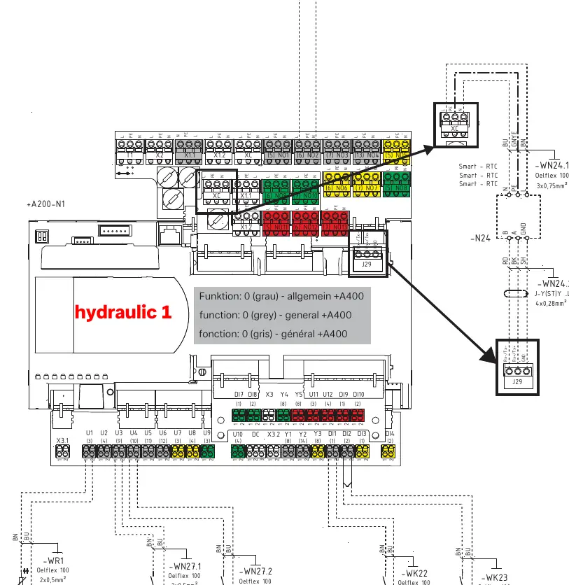
- General (+A400): Standard operation settings.
- Domestic Hot Water (+A420): Requires connection of the domestic hot water sensor (-R3) and the reversing valve (-YM18).
- Cooling (+A150): Requires connection of the dew point monitor (-N5) and the heating/cooling change-over switch (-K28).
- Sensors & Inputs: Includes connections for the external wall sensor (-WR1), Smart-Grid inputs, and EVU-Sperre (utility block contactor).
Manufacturer information
Dimplex
Practical help
Common problems
Remote fault indicator not working
Verify the wiring connection of the -H5 remote fault indicator to the terminal block.
Domestic hot water not heating
Check the wiring of the -R3 domestic hot water sensor and the -YM18 reversing valve.
Cooling function not active
Ensure the dew point monitor (-N5) and the heating/cooling change-over switch (-K28) are correctly wired.
Before use
- Verify that the electrical distribution (+A300) is correctly fused.
- Confirm all sensor connections (external wall sensor, hot water sensor) are secure.
- Check that the communication bus (FBUS 1) between the heat pump and Hydrobox is connected.
- Verify the wiring of Smart-Grid and EVU-Sperre inputs if required by the installation.
- Ensure the hydraulic circuit is properly installed and leak-free.
Images and diagrams
- Electrical layout: Shows the interconnection between the heat pump, Hydrobox, and power distribution.
- Hydraulic diagram: Illustrates the flow path and component placement for the heating system.
- Plug-in diagrams: Detail the specific terminal connections for various system functions like hot water and cooling.
Model compatibility
- Wiring configurations vary based on the selected function (General, Hot Water, or Cooling).
- Ensure cable cross-sections match the specifications provided in the diagrams (e.g., 1.5mm², 2.5mm²).

Manual page author
David Miller
Documentation analyst
Organizes user manual content into clear summaries, with attention to model details, product context, and everyday usability.