HVAC / Heat Pumps
Installation and Operating Instruction for Dimplex SI 130TU Heat Pump
Quick guide for the Dimplex SI 130TU brine-to-water heat pump. Includes installation, electrical connection, commissioning, maintenance, and technical specifications.
Table of contents
Manual images
Click an image to enlargeQuick guide from the manual
This document provides essential installation and operating instructions for the Dimplex SI 130TU brine-to-water heat pump. It is intended for use by qualified personnel. The heat pump is designed for indoor installation and must be operated in accordance with local regulations.
Safety information
- Qualified personnel only: Work on the heat pump must only be performed by authorized and qualified after-sales service technicians.
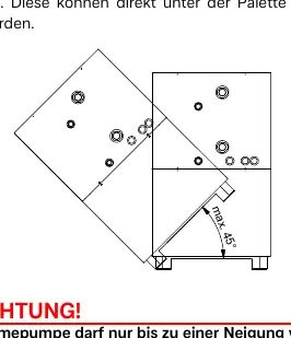
- Transport: The heat pump must not be tilted more than 45 degrees in any direction during transport.
- Power supply: Always disconnect all circuits from the power supply before opening the device. Wait at least 5 minutes after disconnecting to allow electric charges to dissipate.
Product description
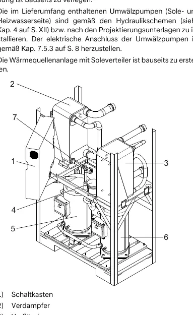
The SI 130TU is a brine-to-water heat pump for indoor installation. It features a hermetically sealed refrigeration circuit containing R410A refrigerant. The unit includes a switch box and an integrated heat pump manager.
Installation
The heat pump must be installed in a frost-free, dry room on an even, smooth, and horizontal surface. Ensure a clearance of approximately 1 meter in front of the unit for maintenance access. The unit is not intended for use at altitudes above 2000 meters.
Electrical connection
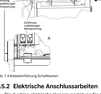
Electrical installation must be carried out by a trained electrician. Ensure a clockwise rotating field; incorrect wiring will prevent the heat pump from starting. Mains cables and signal cables must be inserted separately into the switch box using the designated inlets to prevent interference.
Commissioning
Commissioning must be performed via the heat pump manager. Ensure all connections are installed, the heat source and heating circuits are filled and checked, and the dirt trap is installed in the brine inlet before starting.
Cleaning and maintenance
To prevent sediment buildup in heat exchangers, ensure no impurities enter the system. A dirt trap is supplied and must be installed in the heat source inlet. Clean the filter sieve one day after start-up and periodically thereafter. Use appropriate corrosion protection systems to prevent deposits in the condenser.
Technical specifications
The SI 130TU operates with a heating water flow temperature of 20 to 62 °C and a brine temperature of -5 to 25 °C. The maximum operating overpressure is 3.0 bar. The unit requires a 3-phase 400V supply for the power part and a 230V supply for the heat pump manager.
Manufacturer information
Dimplex
Practical help
Common problems
Heat pump does not start
Check for a clockwise rotating field in the electrical wiring. A warning will be displayed on the heat pump manager.
Fault indicated on display
Consult the 'Faults and troubleshooting' section in the operating instructions of the heat pump manager.
Reduced performance
Check for sediment in heat exchangers; clean the dirt trap in the brine inlet.
Before use
- Ensure the installation room is frost-free and dry.
- Flush the heating system thoroughly before connection.
- Install the supplied dirt trap in the brine inlet.
- Ensure all valves in the brine and heating circuits are open.
- Check that the brine concentration is at least 25%.
- Verify that the heat pump manager is adapted to the heating system.
Specs in practice
- Max. operating overpressure
- 3.0 bar for both heat source and heat sink circuits.
- Operating limits (heating water)
- 20 to 62 °C.
- Electrical protection
- IP 21 degree of protection.
Images and diagrams
- Fig 7.4: Cable inlet for switch box showing the required separation of mains and signal cables.
- Hydraulic integration diagrams (A-XII, A-XIII) illustrate connections for monovalent and bivalent systems.
Model compatibility
- Not intended for use at altitudes above 2000 meters.
- Requires monoethylene glycol or propylene glycol-based antifreeze.
- Minimum brine concentration is 25% (can be extended to 30% for lower temperatures).

Manual page author
David Miller
Documentation analyst
Organizes user manual content into clear summaries, with attention to model details, product context, and everyday usability.