HVAC / Heat Pumps
Installation Guide for Dimplex LIA 0608HXCF M Split Heat Pump
Technical installation guide for the Dimplex LIA 0608HXCF M and 0911HXCF M split heat pumps, covering electrical wiring layouts, hydraulic connections, and sensor integration.
Table of contents
Manual images
Click an image to enlargeQuick guide from the manual
This document provides the electrical and hydraulic installation layouts for the Dimplex LIA 0608HXCF M and LIA 0911HXCF M split heat pumps. It is intended for qualified installers to ensure correct system integration and wiring.
Electrical Layout
The electrical system connects the Split Heat Pump (+A100), the Hydrobox with heat pump manager (+A200), and the electrical distribution system (+A300). Key requirements include:
- Power Supply: Ensure correct fuse protection (e.g., C13A, C20A, B32A) as specified in the diagram.
- Communication: Use the FBUS 1 connection (4x0.28mm²) for data exchange between the heat pump and the Hydrobox.
- Cabling: Use specified cable types such as NYM-J (3x6.0mm², 3x4mm²) and Oelflex 100 for control signals.
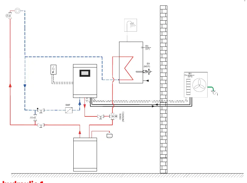
Hydraulic Layout
The hydraulic diagram illustrates the flow and return paths, including the integration of the heat pump, the Hydrobox, and the domestic hot water system. Ensure all valves and sensors are installed according to the schematic provided in the manual.
Wiring Connections (Plug In)
The system supports various external inputs and sensors. Connections are function-specific:
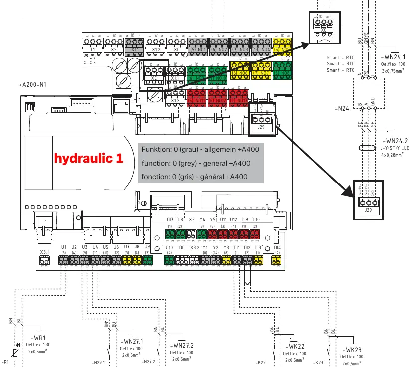
- External Wall Sensor (R1): Connect to the designated terminals.
- Smart-Grid: Inputs for Smart-Grid 1 and 2 integration.
- Utility Block (EVU-Sperre): Connection for utility company blocking signals.
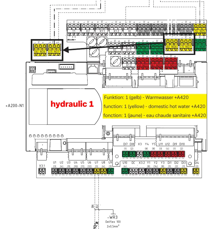
- Domestic Hot Water: Specific wiring for the reversing valve (-YM18) and flange heater (-E9).
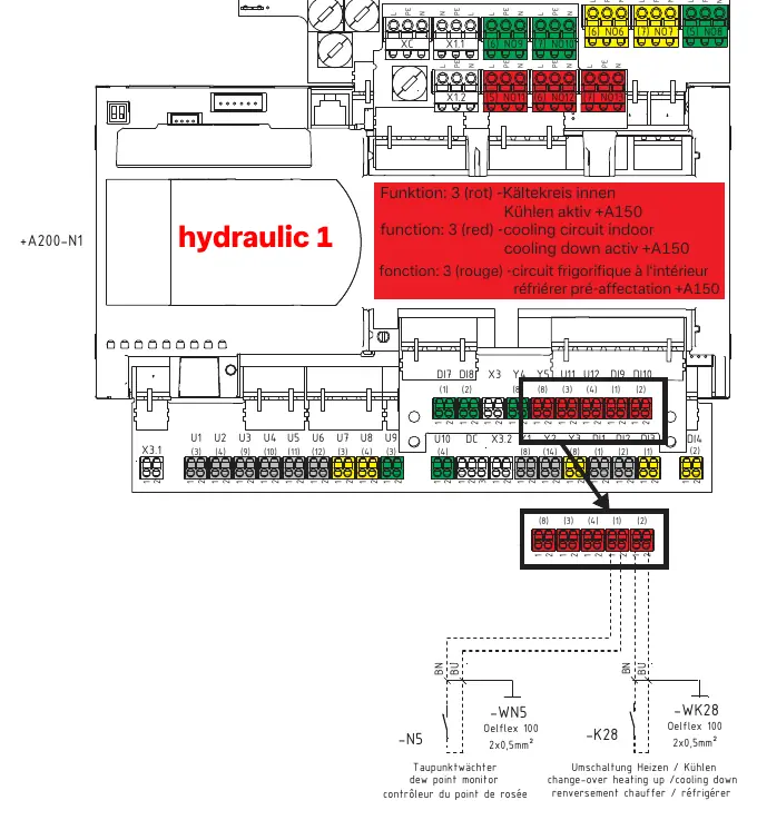
- Cooling Circuit: Specific wiring for cooling mode activation (+A150).
Manufacturer information
Dimplex
Practical help
Common problems
Incorrect communication between units
Verify the FBUS 1 connection (4x0.28mm²) between +A100 and +A200 is wired correctly.
Hot water system not activating
Check the wiring for the reversing valve (-YM18) and flange heater (-E9) against the diagram on page 4.
Cooling mode not active
Ensure the cooling circuit wiring (+A150) is correctly connected as shown on page 6.
Before use
- Verify the power supply matches the 230V requirements.
- Check cable cross-sections: 3x6.0mm² for Hydrobox, 3x4mm² for Heat Pump.
- Confirm all sensors (R1, R3) are connected to the correct terminals.
- Ensure the FBUS 1 communication cable is properly shielded.
- Check the EVU-Sperre (utility block) wiring if required by local regulations.
Images and diagrams
- Page 1: Electrical layout showing connections between Heat Pump, Hydrobox, and Distribution.
- Page 2: Hydraulic circuit diagram.
- Page 3: General plug-in wiring for sensors and Smart-Grid.
- Page 4: Specific wiring for domestic hot water components.
- Page 6: Wiring for cooling circuit activation.
Model compatibility
- Compatible with LIA 0608HXCF M and LIA 0911HXCF M models.
- Requires specific function-based wiring (0, 1, 2, 3) depending on system configuration.

Manual page author
David Miller
Documentation analyst
Organizes user manual content into clear summaries, with attention to model details, product context, and everyday usability.