HVAC / Heat Pumps
Installation Guide for Dimplex M Flex Heat Pump
Technical installation and wiring guide for the Dimplex M Flex heat pump series. Includes detailed electrical layouts, hydraulic diagrams, and connection instructions for heating, hot water, and cooling circuits.
Table of contents
Manual images
Click an image to enlargeQuick guide from the manual
This document provides the electrical and hydraulic installation layouts for the Dimplex M Flex heat pump series (models 0609HBC and 0916HBC). It is intended for qualified installers to ensure correct system integration. The guide covers power supply requirements, sensor connections, and specific wiring configurations for domestic hot water, heating, and cooling circuits.
Electrical Layout Overview
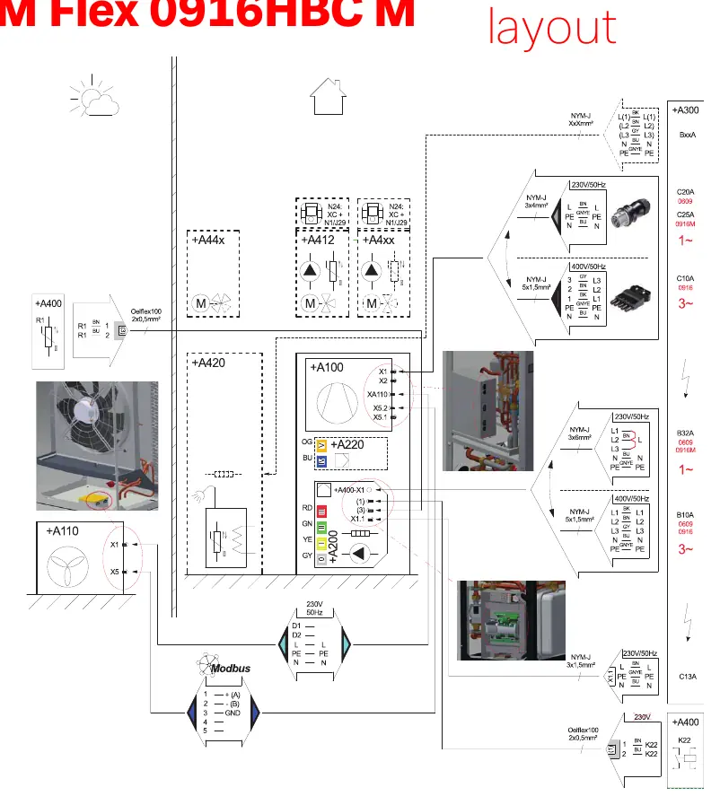
The electrical layout defines the power supply requirements for the heat pump unit. Depending on the specific model and configuration, the system supports 230V/50Hz or 400V/50Hz power supplies. The layout specifies the use of NYM-J cables for power and Oelflex 100 cables for control and sensor signals.
Hydraulic Layout
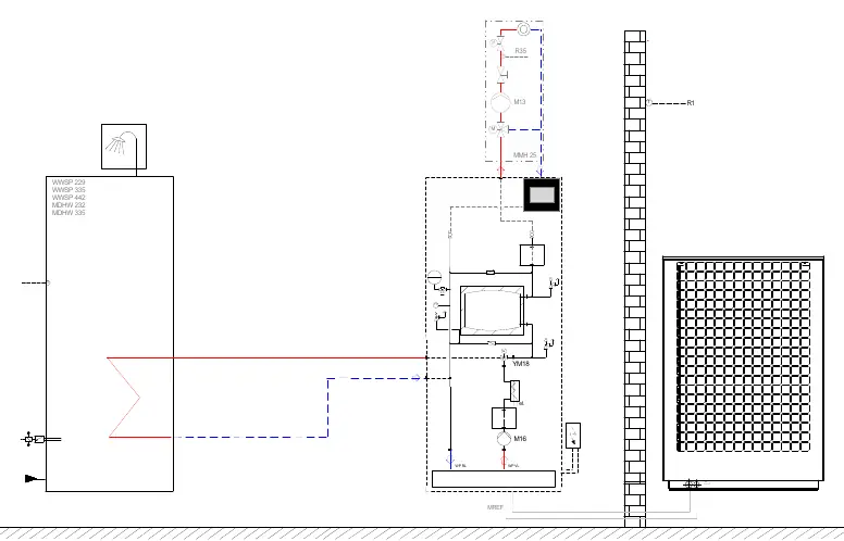
The hydraulic diagram illustrates the connection points for the heat pump, domestic hot water storage tanks (WWSP/MDHW series), and circulation pumps. It highlights the integration of sensors (R1, R3, R35) and valves (YM18, YM16) necessary for proper system operation.
Wiring Connections
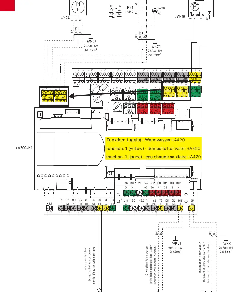
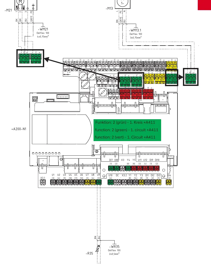
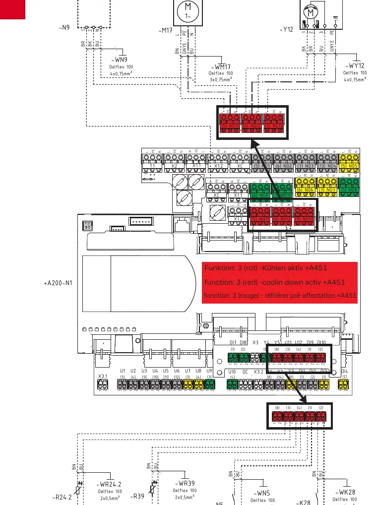
The system utilizes the +A200-N1 controller as the central hub for all connections. Wiring is organized into specific functional blocks, often color-coded on the terminal board to assist with installation:
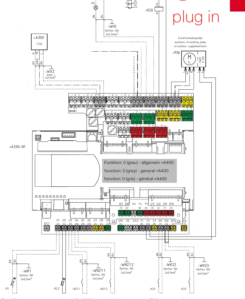
- General (+A400): Basic system connections including external wall sensors and utility block signals.
- Domestic Hot Water (+A420): Connections for the hot water sensor (-R3), circulation pump (-M24), and reversing valve (-YM18).
- Heating Circuit (+A411): Connections for the 1st heating circuit, including the mixer (-M21) and pump (-M13).
- Cooling Circuit (+A451): Connections for cooling functions, including the dew point monitor (-N5) and heating/cooling reversing valve (-Y12).
Technical Specifications and Components
The installation relies on specific components and cable types:
- Cables: Oelflex 100 (various cross-sections like 2x0.5mm², 2x0.75mm², 3x0.75mm²) for control signals; NYM-J (various cross-sections like 3x1.5mm², 5x1.5mm²) for power supply.
- Sensors: Various sensors (R1, R2.2, R3, R35, R39) are used to monitor temperatures in different circuits.
- Relays: K20, K21, K28, K31 are used for switching auxiliary heaters, hot water, and heating/cooling modes.
Manufacturer information
Dimplex
Practical help
Common problems
Incorrect wiring of control signals
Verify that Oelflex 100 cables are connected to the correct terminal blocks (X1, X2, XC) on the +A200-N1 controller as per the specific function diagram.
System not recognizing hot water or heating demand
Check the connection of the respective sensors (-R3 for hot water, -R35 for heating circuit) to the controller.
Power supply mismatch
Ensure the power supply (230V/50Hz or 400V/50Hz) matches the specific requirements of the installed model (0609HBC or 0916HBC).
Before use
- Verify the heat pump model (0609HBC or 0916HBC).
- Confirm the power supply voltage matches the electrical layout.
- Ensure all sensors (R1, R3, R35, etc.) are securely connected to the designated terminals.
- Check that all pumps (M13, M16, M24, M17) are wired according to the specific function diagram.
- Verify that the correct cable types (NYM-J for power, Oelflex 100 for control) are used.
Images and diagrams
- The diagrams use color-coded terminal blocks (Green, Yellow, Red) to indicate specific functions (General, Hot Water, Heating, Cooling).
- Dashed lines in diagrams represent control signal wiring, while solid lines represent power supply wiring.
Model compatibility
- Compatible with M Flex 0609HBC and 0916HBC models.
- Supports integration with WWSP and MDHW series hot water storage tanks.

Manual page author
Michael Turner
Technical manual editor
Reviews PDF manuals for structure, safety notes, and practical product details so readers can find the right information quickly.