Electronics / Evaluation Boards
User Guide for Diodes 10W AP3928 EV1 Evaluation Board
A comprehensive user guide for the Diodes 10W AP3928 EV1 evaluation board. This document covers technical specifications, connection instructions, circuit descriptions, and performance test data for the 18V/550mA power supply application.
Table of contents
Manual images
Click an image to enlargeQuick Start Guide
The AP3928 EV1 evaluation board is preset to provide an 18V/550mA output. Follow these steps to connect and operate the board:
- Ensure the AC source is switched OFF or disconnected before making any connections.
- Connect the AC line wires of your power supply to the L and N connectors located on the left side of the board.
- Turn on the AC main switch.
- Measure the +V and GND connectors to verify the correct output voltage of 18V.
CAUTION: This evaluation board is non-isolated. Do not touch any electrical connections while the board is powered, as all components are coupled to high voltage potential.
Product Overview
The AP3928 is an off-line universal AC voltage input step-down regulator. The EV1 evaluation board serves as a design example for a cost-effective 9.9W single output 18V/550mA power application, suitable for home appliances such as AC fans, rice cookers, air conditioners, coffee machines, soy milk machines, and auxiliary power for IoT devices.
Technical Specifications
Key performance parameters for the evaluation board include:
- Input Voltage: Universal 85V to 265V AC.
- Output: 18V nominal, 550mA rated output current.
- Standby Power: Less than 30mW at no load.
- Efficiency: High light-loading and average efficiency meeting DOE and CoC requirements.
- Operating Temperature: -20°C to 85°C.
- Protection Features: Includes Over-Temperature Protection (OTP), Over-Load Protection (OLP), Open Loop Detection (OLD), and Short Circuit Protection (SCP).
Circuit Description
The board design utilizes a non-isolated buck topology:
- Input EMI Filtering: Composed of fusible resistor F1, rectifier bridge DB1, filtering inductor L1, and capacitors C1 and C2. F1 acts as a flame-proof, fusible wire-wound resistor to limit inrush current and provide short-circuit protection.
- Control IC: The AP3928 integrates a 700V power MOSFET and control circuitry in an SO-8 package.
- Output Rectification: Uses free-wheeling diode D3 (ultra-fast) and feedback diode D1.
- Output Feedback: Voltage across L2 is rectified and divided by R1 and R2/R3 to provide a feedback signal to the FB pin of the AP3928.
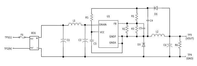
Schematic and Bill of Materials
The evaluation board schematic illustrates the connection of the AP3928 controller with the input filtering, rectification, and feedback components. The bill of materials includes 18 components, featuring the AP3928 IC, Rubycon electrolytic capacitors, and Wurth inductors.
System Testing and Performance
The manual provides detailed test results for the evaluation board, including:
- Input & Output Characteristics: Standby power, efficiency, and line/load regulation data.
- Key Performance Tests: Start-up performance, rise time, internal MOSFET drain-source voltage stress, output ripple and noise, and dynamic response.
- Protection Tests: Verification of SCP, OLD, and OLP functionality.
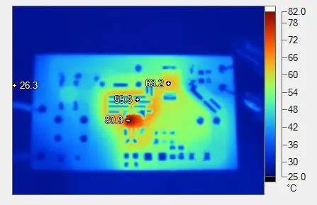
- Thermal Test: Surface temperature observations of the AP3928 under full load.
- EMI Scan: Conducted EMI test results confirming compliance with EN55022 Class B requirements.
Manufacturer information
Diodes Incorporated
Practical help
Common problems
High voltage hazard
The board is non-isolated. Do not touch any electrical connections while the board is powered.
Output instability
Ensure the load does not exceed the rated 550mA. Overload protection triggers at approximately 750mA.
Voltage tolerance
The output voltage is maintained within a ±5% tolerance at rated output current.
Before use
- Ensure AC source is switched OFF or disconnected.
- Verify AC line wires are connected to 'L' and 'N' terminals.
- Ensure output load is within 550mA limit.
- Discharge buck capacitors before starting tests.
Specs in practice
- Input Voltage
- Universal 85V to 265V AC input range.
- Standby Power
- Less than 30mW power consumption at no load.
- Operating Temperature
- Safe operation between -20°C and 85°C.
Images and diagrams
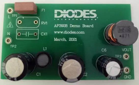
- Figure 1 & 2: Top and bottom views of the evaluation board.
- Figure 3: Schematic diagram of the evaluation board.
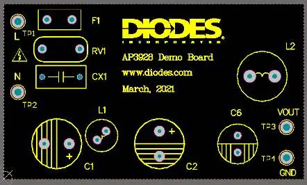
- Figure 4 & 5: PCB layout top and bottom views.
Model compatibility
- Designed for non-isolated home appliances (fans, rice cookers, etc.) and auxiliary power for IoT devices.

Manual page author
Emily Carter
User documentation editor
Prepares concise manual descriptions and highlights the most useful setup, operation, and maintenance information for readers.