Electronics / Evaluation Boards
User Guide for Linear Technology 1171A Demonstration Circuit
Quick start guide for the Linear Technology 1171A synchronous buck converter demonstration circuit. Includes setup procedures, jumper configurations for mode selection, rail tracking options, and performance specifications.
Table of contents
Manual images
Click an image to enlargeQuick Start Guide for Demonstration Circuit 1171A
The 1171A demonstration circuit is a single-output synchronous buck converter featuring the LTC3851EGN. It is designed to evaluate the performance of the LTC3851EGN controller. The board is available in two versions: DC1171A-A (uses an on-board sense resistor) and DC1171A-B (uses DCR sense circuit for higher efficiency).
Setup Procedure
Follow these steps to set up the demonstration circuit for evaluation:
- Jumper Configuration: Place jumpers in the following positions: JP1 to 400k, JP2 to On, and JP3 to CCM.
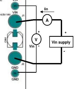
- Power Connection: With the power off, connect the input power supply to the Vin and GND terminals.
- Power Up: Turn on the power at the input. Ensure the input voltage does not exceed 14V.
- Voltage Check: Verify the output voltage is between 1.470V and 1.530V. If there is no output, temporarily disconnect the load to ensure it is not set too high.
- Load Adjustment: Once the output voltage is established, adjust the loads within the operating range to observe regulation, ripple, and efficiency.
Measurement Technique
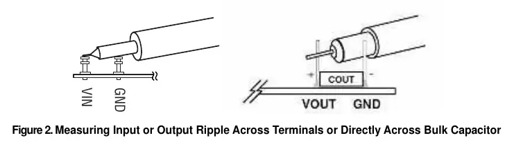
When measuring input or output voltage ripple, avoid using a long ground lead on the oscilloscope probe. To obtain accurate readings, touch the probe tip directly across the Vin or Vout and GND terminals.
Frequency Synchronization and Mode Selection
The board allows for different operating modes by adjusting jumper JP3. Refer to the following configurations:
- CCM Operation: JP1 set to 400k, JP4 set to CCM.
- Pulse Skip Operation: JP1 set to 400k, JP4 set to P.S.
- Burst Mode Operation: Requires a 100k resistor between JP4 pin 1 and pin 2; JP1 set to 400k, remove JP4 jumper.
- External Clock Synchronization: JP1 set to EXTCLK, JP4 set to BURST. Apply the external clock to the MODE/PLLIN pin.
Rail Tracking
The circuit is configured for an on-board soft start. The ramp rate can be adjusted by changing the value of C24. The board can also be modified to track an external reference. Refer to the data sheet for specific resistor and capacitor modifications required for different tracking options.
Technical Specifications
- Input Voltage Range: 4.5V to 14V
- Output Voltage: 1.5V ±2%
- Nominal Switching Frequency: 400kHz
- Efficiency: Up to 90% typical (depending on version and load)
Practical help
Common problems
No output voltage
Temporarily disconnect the load to ensure it is not set too high.
Input voltage damage
Ensure the input voltage does not exceed 14V.
Inaccurate ripple measurement
Avoid long ground leads on the oscilloscope probe; touch the probe tip directly across the Vin/Vout and GND terminals.
Before use
- Verify input power supply is off before connection.
- Ensure input voltage is within the 4.5V to 14V range.
- Configure jumpers JP1, JP2, and JP3 according to the desired operating mode.
- Check that the load is within the operating range.
Specs in practice
- Input Voltage Range
- 4.5V to 14V DC.
- Output Voltage
- 1.5V nominal, with ±2% tolerance.
- Switching Frequency
- 400kHz nominal.
Images and diagrams
- Figure 1 illustrates the proper measurement equipment setup for Vin and Vout.
- Figure 2 demonstrates the correct oscilloscope probe technique for measuring ripple.
Model compatibility
- Compatible with LTC3851EGN controller.
- DC1171A-A uses an on-board sense resistor.
- DC1171A-B uses DCR sense circuit for improved efficiency.

Manual page author
Michael Turner
Technical manual editor
Reviews PDF manuals for structure, safety notes, and practical product details so readers can find the right information quickly.