Electronics / Evaluation Boards
User Manual for Linear Technology Demo Circuit 1376A-A/-B
Quick start guide and technical manual for the Linear Technology Demo Circuit 1376A-A and 1376A-B, featuring the LTC3555-1 and LTC3555-3 USB power manager and triple step-down DC/DC converter. Includes setup procedures, performance...
Table of contents
Manual images
Click an image to enlargeQuick guide from the manual
The Demo Circuits 1376A-A and 1376A-B are evaluation boards for the LTC3555-1 and LTC3555-3, which are highly integrated power management and battery charger ICs for Li-Ion/polymer battery applications. These circuits are designed for USB applications and feature a switching PowerPath manager, an ideal diode, and three general-purpose synchronous step-down switching regulators.
Performance Summary
Specifications are at TA = 25°C:
- VBUS Input Supply Range: 4.35V to 5.5V
- VOUT Output Voltage: 3.4V to 4.7V (Mode and load dependent)
- LDO3V3 Output Voltage: 3.3V
- VFLOAT (BAT Regulated Output Voltage): 4.179V-4.221V (LTC3555-1) / 4.079V-4.121V (LTC3555-3)
- IBAT (Constant Current Mode Charge Current): 460mA - 532mA (RPROG = 2kΩ)
- VOUT1 Output Voltage: 3.3V
- VOUT2 Output Voltage: 3.0V (Servo Voltage = 0.8)
- VOUT3 Output Voltage: 1.5V (Servo Voltage = 0.8)
Quick Start Procedure
Follow these steps to evaluate the performance of the LTC3555-1 and LTC3555-3:

- Ensure the DC590 software is installed. Connect the DC1376A, DC590, and Host PC.
- Run QuikEval.exe to detect the demo board and launch the LTC3555 Graphical User Interface (GUI).
- If using an external supply, connect a 0-6V, 1.5A supply to VBUS and GND. Do not use USB input and external supply simultaneously.
- Set JP1 (NTC) to INT for the onboard resistor network, or EXT for an external NTC resistor.
- Set JP2 and JP3 (ILIM0 and ILIM1) to LO for initial power-up.
- Connect adjustable loads and meters to LDO3V3, VOUT, VOUT1, VOUT2, and VOUT3 terminals as specified in the manual.
- Connect a Li-Ion or Li-Polymer battery to the BAT and GND terminals.
- Use the GUI to set VBUS to 5V and configure the CURRENT LIMIT SETTING.
- Monitor charge current, output voltages, and battery behavior during discharge and charge cycles.
Input Current Limit Settings
The input current limit is configured using jumpers ILIM0 and ILIM1:
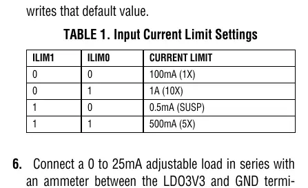
- 0, 0: 100mA (1X)
- 0, 1: 1A (10X)
- 1, 0: 0.5mA (SUSP)
- 1, 1: 500mA (5X)
Application Information
The demo circuit includes specific RC networks to ensure stability:
- Input Damping: The RC network of C5 and R26 dampens input source inductances. This is generally not required when using a USB cable.
- Battery Simulation: The RC network of C15, R9, R10, and R11 simulates a low-impedance battery, allowing proper operation without a battery or with a battery simulator.
- Stability: The LTC3555-1/LTC3555-3 requires a minimum of 10uF on the VOUT pin in 10X mode for stability.
Official resources from the manual
Practical help
Common problems
Oscillations during evaluation
Verify with a real battery under the same conditions, as it is difficult to match the impedance of a real battery with a simulator.
Input current limit exceeded
When the input current limit is reached, power is automatically drawn from the battery to supply VOUT.
Instability in battery charger section
Ensure the C15 RC network is present to simulate low impedance, especially when using a battery simulator.
Before use
- Install the QuikEval software.
- Do not use the USB input and an external power supply at the same time.
- Verify the battery type is Li-Ion or Li-Polymer.
- Set jumpers JP2 and JP3 to LO for initial power-up.
- Use twisted pair leads for power supply connections to minimize inductance.
Specs in practice
- VBUS Input Supply Range
- 4.35V to 5.5V operating range for the demo circuit.
Images and diagrams
- Figure 1 shows the Graphical User Interface (GUI) used to control regulator modes and current limits.
- Figure 2 illustrates the proper measurement equipment setup, including load connections and voltmeter/ammeter placement.
Model compatibility
- Designed for Li-Ion/polymer battery applications.
- Requires a minimum of 10uF on the VOUT pin in 10X mode for stability.

Manual page author
David Miller
Documentation analyst
Organizes user manual content into clear summaries, with attention to model details, product context, and everyday usability.