Automotive / RV Appliances
Installation Manual for Dometic 10-Series Refrigerator
Quick guide for installing and connecting the Dometic 10-Series refrigerator (RML 10.4, RML 10.4S, RML 10.4T). Includes safety warnings, ventilation requirements, gas and electrical connection steps, and technical specifications.
Table of contents
Manual images
Click an image to enlargeQuick guide from the manual
This manual provides essential instructions for the installation and connection of the Dometic 10-Series refrigerator (RML 10.4, RML 10.4S, RML 10.4T). Proper installation is critical for safety and performance.
Safety instructions
- Explosion hazard: Never open the absorber unit; it is under high pressure. Use only the gas pressure specified on the type plate.
- Fire hazard: Use only propane or butane gas. Do not use naked flames to check for leaks. Ensure clean handling of sealants.
- Health hazard: Do not operate if visibly damaged. Repairs must be performed by qualified personnel.
- Asphyxiation: When disposing of the old device, remove doors and leave shelves inside to prevent accidental enclosure.
Installation
The refrigerator must be installed in a draft-proof location in caravans or motor homes.
Preparing the installation
- The vehicle must be parked horizontally (max 3° angle).
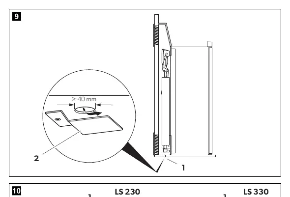
- Maintain a minimum distance of 5 mm from the floor to allow the door to open.
- Ensure no heat-sensitive components (cables, ducts) are near the gas burner.
Draft-proof installation
To prevent combustion air from being extracted from the interior, use a flexible seal between the rear panel and the vehicle interior. Three versions are available (Fig. 8):
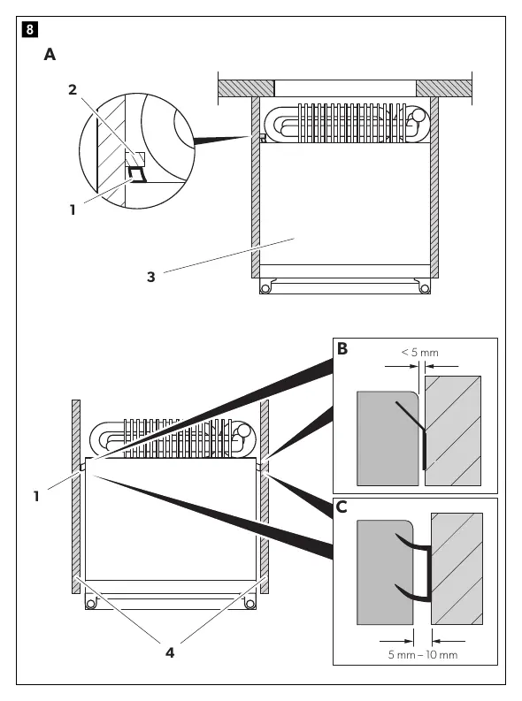
- Stop bar (A): Glue a flexible sealing lip to a stop bar behind the refrigerator.
- Side gap up to 5 mm (B): Glue sealing lips to the side of the furniture.
- Side gap 5-10 mm (C): Glue double-lipped sealing to the side of the furniture.
Ventilation
- Install air inlet and outlet vents in the outer wall.
- Distance between inlet and outlet vents must be at least 1050 mm.
- If the minimum distance cannot be met, install a roof vent.
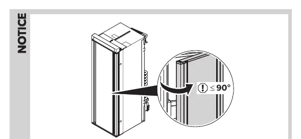
- Use original Dometic ventilation grills (LS230 or LS330).
Connecting the refrigerator
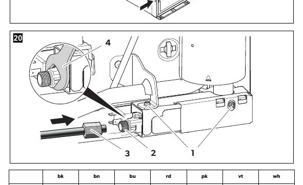
Gas supply
- Connection must be performed by a specialist.
- Use a metal-sealed screw connection.
- Always use a backup wrench (17 mm) when connecting the gas supply line.
- Perform a leak test and flame test after installation.
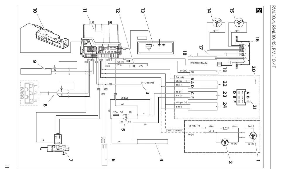
DC and AC power
- DC power: Connect to the battery. The electronics use the D+ signal to detect the running engine. Protect the heating element supply line with a 20 A fuse and the electronics supply line with a 2 A fuse.
- AC power: Connect using the device plug. Do not cut off the plug.
Manufacturer information
Dometic
Practical help
Common problems
Poor cooling performance
Check ventilation (ensure min 1050mm distance between vents), check rear wall distance (15-25mm), and ensure no heat-sensitive components are near the burner.
Gas smell or leak
Switch off the device, avoid flames/sparks, air the room well, and contact an authorized specialist.
Condensation inside the refrigerator
Check door seal, ensure food is not stored while too warm, and ensure the condensation drain has a constant slope.
Before use
- Ensure the vehicle is parked horizontally (max 3° angle).
- Verify gas type (propane/butane) and pressure match the type plate.
- Ensure ventilation grills are original Dometic parts.
- Check that the power supply voltage matches the type plate.
- Ensure the installation is draft-proof.
Specs in practice
- Gas connecting pressure
- 30 mbar
- Climate class
- SN
- Power consumption
- 170 W (230 V / 12 V)
- Gross capacity
- 133 liters
Images and diagrams
- Fig 1: Door clearance requirements (5mm).
- Fig 4-6: Ventilation requirements and distances.
- Fig 8: Draft-proof installation methods (A, B, C).
- Fig 21: Circuit diagram for electrical connections.
Model compatibility
- Suitable for installation in caravans and motor homes.
- RML 10.4 and RML 10.4T feature a CI bus interface for control via central vehicle display.

Manual page author
Emily Carter
User documentation editor
Prepares concise manual descriptions and highlights the most useful setup, operation, and maintenance information for readers.