Automotive / RV Appliances
User Manual for Dometic DuraLite 100E Portable Solar Kit
Quick guide for the Dometic DuraLite 100E Portable Solar Kit. Includes setup instructions, solar controller operation, wiring diagrams, and troubleshooting steps for optimal charging.
Table of contents
Manual images
Click an image to enlargeQuick guide from the manual
The Dometic DuraLite 100E is a portable solar kit designed for charging batteries. Note that the GP-DuraLITE-100 base kit includes an integrated 30-amp solar controller, while the GP-DuraLITE-100E expansion kit does not. The base kit is intended for pre-wired RVs and is not compatible with portable power stations unless the controller is disconnected. The expansion kit is compatible with portable power stations.
Setup and installation
To set up the solar panel:
- Locate a sunlit area free from obstructions like branches.
- Remove the kit from the carrying case.
- Unclip the side latches and fold the panels outward.
- Extend the support legs to their maximum length and lock them in position.
- Place the panel facing the sun.
- Stabilize the panel by inserting a tent peg into the grommet hole at the base of each leg.
Important: Avoid any shading, as even small objects can significantly reduce power output. Frequently adjust the panel direction to track the sun for maximum output.
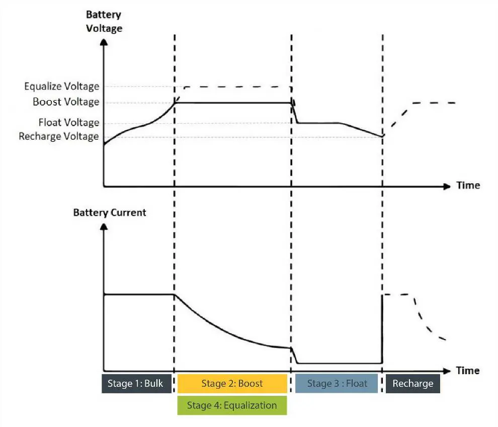
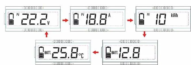
Solar controller operation
The solar controller manages the charging process. It requires a battery connection to function (minimum 8V). The display cycles through PV voltage, PV current, PV power, battery voltage, and battery temperature.
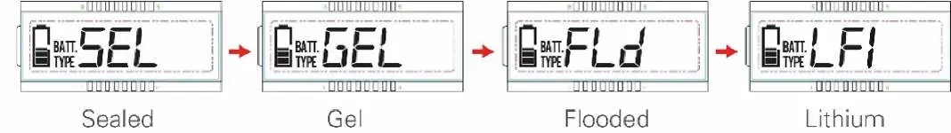
Setting battery type:
- Press and hold the SET button for 5 seconds under the battery voltage interface.
- Press the MENU button when the battery type interface flashes.
- Press the SET button to confirm the selection (Sealed, Gel, Flooded, Lithium 1, or Lithium 2).
Troubleshooting
If the system is not functioning as expected:
- No power to LCD: Check all connections between the kit, controller, and battery. Ensure battery voltage is above 8V.
- Overvoltage error (flashing battery icon): The battery voltage is too high. Disconnect the solar controller and apply a load to the battery to drain it.
- Over discharge error (flashing empty battery icon): The battery voltage is too low. Connect the solar kit to charge the battery.
- Inaccurate voltage reading: Check for loose connections, long wire runs, or small wire gauges causing voltage drop.
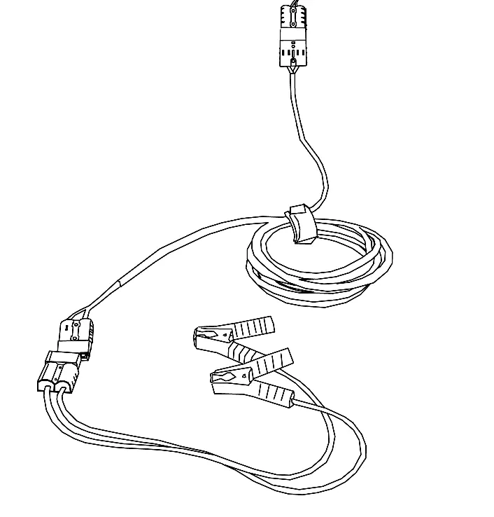
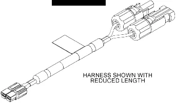
Expansion and wiring
You can expand the system up to 300 watts by connecting up to two expansion kits. Use the branch connector to link the expansion panels to the solar controller. Ensure all connections are made red-to-red and black-to-black, and listen for a click to confirm a secure connection.
Manufacturer information
Dometic
Practical help
Common problems
No power to LCD screen
Check connections between the kit, controller, and battery. Ensure battery voltage is above 8V.
Overvoltage error (flashing battery icon)
Battery voltage is too high. Disconnect the solar controller and apply a load to the battery to drain it.
Over discharge error (flashing empty battery icon)
Battery voltage is too low. Connect the solar kit to charge the battery.
Inaccurate voltage reading
Check for loose connections, long wire runs, or small wire gauges causing voltage drop.
Before use
- Ensure the area is sunlit and free of obstructions.
- Check all wiring connections for tightness and security.
- Verify battery polarity before connecting.
- Ensure the battery is connected to the controller first.
- Check that the battery type setting matches your battery.
Specs in practice
- Nominal System Voltage
- 12 VDC
- Rated Charge Current
- 30A
- Max PV Open Circuit Voltage
- 50V
- Battery Types Supported
- Sealed, Gel, Flooded, Lithium 1, and Lithium 2
Images and diagrams
- Wiring Diagram: Shows how to connect the base kit and expansion kits using the 3-way expansion harness.
- Controller Display: Cycles through PV voltage, current, power, battery voltage, and temperature.
Model compatibility
- GP-DuraLITE-100 includes a solar controller; GP-DuraLITE-100E does not.
- GP-DuraLITE-100 is not for portable power stations unless the controller is disconnected.
- GP-DuraLITE-100E is compatible with portable power stations.

Manual page author
David Miller
Documentation analyst
Organizes user manual content into clear summaries, with attention to model details, product context, and everyday usability.