Tools / Power Tools
Installation and Operation Guide for Draper Dual Roller 12V Battery FlexShade
A comprehensive installation and operation guide for the Draper Dual Roller 12V Battery FlexShade. Includes detailed instructions for mounting endcaps, installing surface and pocket headboxes, programming limit switches, and battery...
Table of contents
Manual images
Click an image to enlargeQuick Guide from the Manual
This document provides installation and operation instructions for the Draper Dual Roller 12V Battery FlexShade (DFBA). Before beginning, ensure you have the necessary tools: pencil, power drill, tape measure, and level. The installer is responsible for selecting appropriate mounting hardware for the site conditions. Always verify that the wall or ceiling structure is sufficient to support the weight of the unit.
Safety Information
- Installation and calibration must be performed by an authorized, qualified professional.
- Electrical work and wiring must be completed by a qualified electrician.
- Do not wire motors in parallel without written permission from Draper, Inc.
- Ensure the unit is level and square during installation.
- Turn off power before connecting switches, wires, or controls.
- Never leave the area while operating the unit during installation or maintenance.
Components Overview
The system consists of the following main parts:
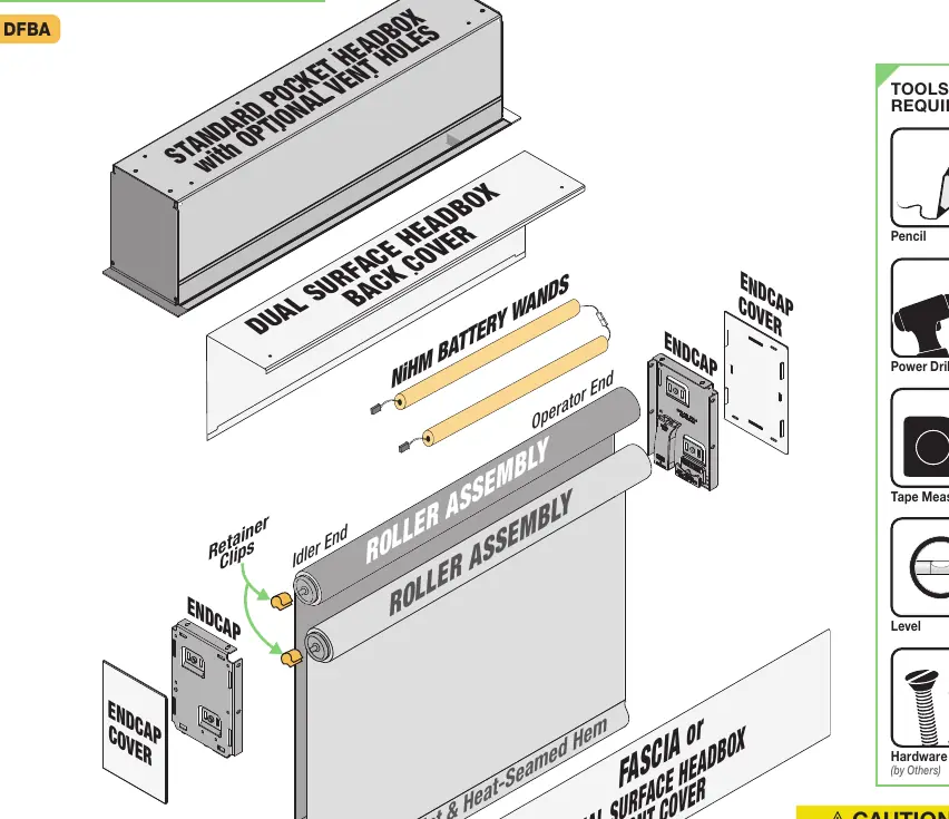
- Headbox: Available in Surface or Pocket configurations.
- Roller Assembly: Dual rollers with aluminum slat and heat-seamed hem.
- Endcaps: Left-hand and right-hand brackets with snap-on covers.
- Battery Wands: NiHM battery packs for motorized operation.
Mounting Endcaps
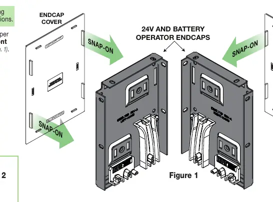
- Snap endcap covers onto the endcaps, ensuring correct orientation (Left-Hand/Right-Hand, Front/Back).
- Mark the wall, jamb, or ceiling for placement.
- Drill starter holes if necessary.
- Mount endcaps using appropriate fasteners for the surface.
Installing Fascia
- Place the groove along the top of the fascia over the endcaps.
- Snap the fascia into place. It is not fully seated until it clicks on both ends.
- Check for a secure fit; if loose, secure with an additional fastener.
Headbox Installation
Surface Headbox
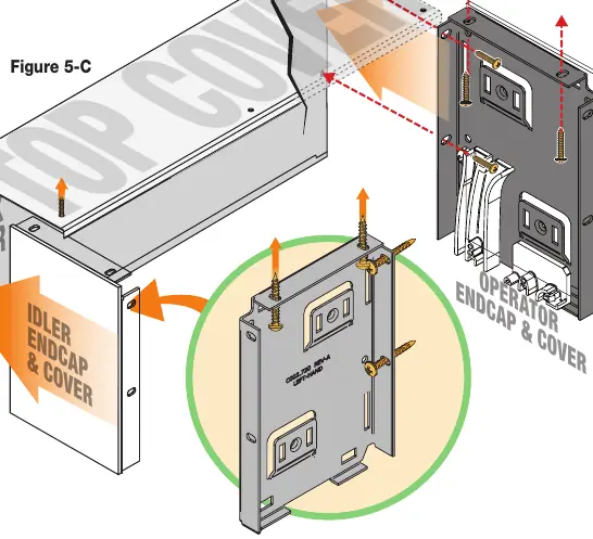
- Place endcaps into the top/back cover piece.
- Mark the headbox for drilling using the pre-drilled holes in the endcaps.
- Drill holes in the back (wall mount) or top (ceiling mount) of the cover.
- Attach the assembly to the wall or ceiling using appropriate hardware. A minimum of two screws per endcap is required.
Pocket Headbox
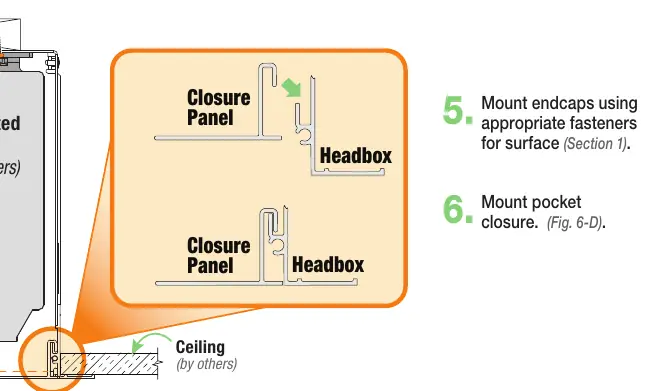
- Lift the headbox into the mounting position.
- Mark the location of pre-drilled pocket mounting holes and endcap mounting holes.
- Drill starter holes and mount the pocket headbox using appropriate fasteners.
- Mount endcaps and the pocket closure panel.
Battery and Motor Setup
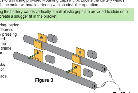
- Mount battery wands to the wall using provided clips. Position them to reach the motor without interfering with shade operation.
- Place the rear shade spring-loaded pin into the idler endcap.
- Depress the pin by pressing the roller toward the endcap and slip the operator end into the slots on the operator endcap.
- Connect battery packs together and to the motor.
- Repeat the process for the front shade.
Limit Switch Adjustments
The motor must be installed so limit switches are pointed down. To set limits:
- Check Rotation: Press the Up button. If the shade rises, rotation is correct. If it lowers, press the 'my/stop' button until the shade moves up and down to modify direction.
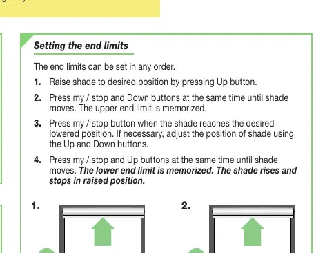
- Set Upper Limit: Raise the shade to the desired position. Press 'my/stop' and Down buttons simultaneously until the shade moves.
- Set Lower Limit: Lower the shade to the desired position. Press 'my/stop' and Up buttons simultaneously until the shade moves.
Cleaning and Maintenance
The system requires no operational maintenance or lubrication. Clean standard fabrics by vacuuming with a soft brush attachment or using a sponge with mild soapy water. Metal finishes should be cleaned with a clean, dry cloth. Note: Flocké and Phifer SW7000 fabrics must be cleaned with a dry art sponge.
Manufacturer information
Draper Tools
Practical help
Common problems
Shade is telescoping (fabric tracking to one side)
Place a piece of high-quality gaffer tape (approx. 1" wide) on the exposed roller on the side the fabric is being drawn toward.
Incorrect direction of rotation
Press the 'my/stop' button on the RTS control point or motor head until the shade moves up and down to reverse the direction.
Shade falls or fails
Ensure the mounting surface has adequate strength and that all brackets/headboxes are installed level and square.
Before use
- Verify measurements on the label provided with the shade.
- Ensure the unit is installed at the correct width.
- Turn OFF power before connecting electrical components.
- Ensure all hardware is installed level and square.
- Confirm wall/ceiling structure can support the weight of the unit.
Specs in practice
- Limit Switches
- Programmable settings that define the upper and lower travel points of the shade.
- RTS Control Point
- The remote or switch interface used to operate the shade and program motor settings.
Images and diagrams
- Figure 1: Shows endcap orientation and snap-on cover assembly.
- Figure 3: Illustrates battery wand mounting and connection to the motor.
- Figure 5-C: Details the mounting process for the Surface Headbox.
- Figure 6-D: Shows the assembly of the Pocket Headbox and closure panel.
Model compatibility
- Do not wire motors in parallel without written permission from Draper, Inc.
- Headbox must be mounted directly to the ceiling/wall or to continuous blocking secured to the building structure.

Manual page author
Emily Carter
User documentation editor
Prepares concise manual descriptions and highlights the most useful setup, operation, and maintenance information for readers.