Industrial / Signaling Devices
User Manual for Eaton FlexiTech Exit Wall 12M CGLine+ Emergency Light
Comprehensive user guide for the Eaton FlexiTech Exit Wall 12M CGLine+ emergency light. Includes installation, wiring, configuration, testing procedures, and maintenance instructions.
Table of contents
Manual images
Click an image to enlargeQuick Guide
The Eaton FlexiTech Exit Wall 12M CGLine+ is an emergency lighting unit designed for wall mounting. Before first use, ensure the battery is connected and the unit is charged for 24 hours. The device supports both Maintained (always on) and Non-Maintained (on during power failure) modes. Configuration changes require disconnecting the battery for 10 seconds before reconnecting.
Installation
The unit is designed for wall mounting. Follow these steps for installation:
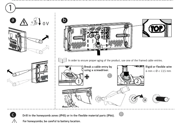
- Preparation: Break a cable entry using a screwdriver.
- Drilling: Drill in the honeycomb zones for IP43 protection or in the flexible material parts for IP66 protection.
- Mounting: For corner fixing, use 4 screws.
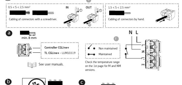
- Wiring: Use a screwdriver to place and remove wires. The unit accepts rigid or flexible wire with a diameter between 6 mm and 13.5 mm.
Wiring and Connections
The unit features specific terminals for power supply. Ensure the cabling is secure. For connectors, use a screwdriver for installation. The unit supports both Maintained and Non-Maintained configurations, which are determined by the wiring setup. Refer to the wiring diagram on the device for specific terminal connections.
Configuration
To change the configuration (Maintained/Non-Maintained or Even/Odd test days), you must:
- Disconnect the battery.
- Wait for 10 seconds.
- Reconnect the battery.
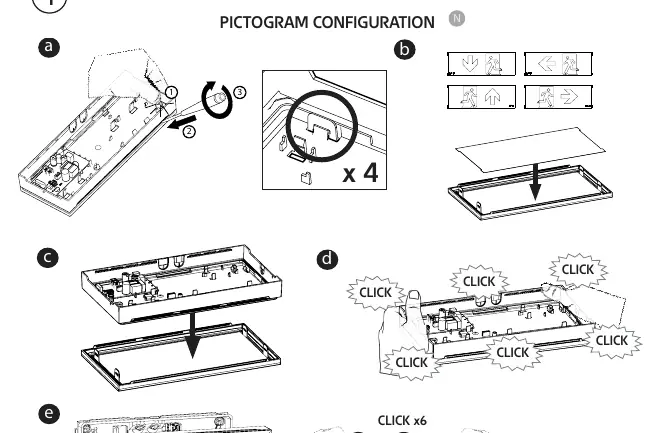
The unit also supports pictogram configuration. Snap the desired pictogram panel into the housing until you hear a click.
Testing and Operation
The device supports magnet testing for quick diagnostics without opening the unit:
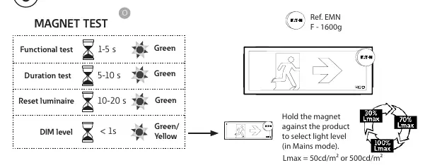
- Functional test: Hold magnet for 1-5 seconds (Green LED).
- Duration test: Hold magnet for 5-10 seconds (Green LED).
- Reset luminaire: Hold magnet for 10-20 seconds (Green LED).
- DIM level: Hold magnet for less than 1 second (Green/Yellow LED).
LED Status Indicators
- Green (Constant): OK.
- Green (Blinking): TEST in progress.
- Green & Yellow (Blinking): COM (Communication).
- Yellow (Constant): 2 seconds duration.
- Yellow (Blinking): 0.5 seconds duration.
Maintenance and Battery Replacement
If the battery duration is insufficient, replace the battery pack (Order code: FT-BATLL1). When the light source reaches the end of its life, the entire luminaire must be replaced. Ensure the installation date is recorded on the battery.
Manufacturer information
Eaton
Practical help
Common problems
Battery duration is insufficient
Replace the battery pack using order code FT-BATLL1.
Light source failure
The light source is not replaceable; replace the entire luminaire.
Configuration changes not taking effect
Disconnect the battery, wait for 10 seconds, and reconnect it to apply new settings.
Before use
- Ensure the battery is connected.
- Charge the unit for 24 hours before first use.
- Verify the operating temperature range (0°C to +45°C).
- Check that the chosen installation surface supports IP43 or IP66 requirements.
- Ensure the correct wiring mode (Maintained vs Non-Maintained) is selected.
Specs in practice
- Non-Maintained
- The emergency light illuminates only during a power failure.
Images and diagrams
- Wiring diagram shows the connection points for power supply and mode selection.
- Pictogram configuration diagram illustrates how to snap the exit sign panel into the frame.
Model compatibility
- Compatible with Controller CGLine+ for advanced duration test configurations.

Manual page author
David Miller
Documentation analyst
Organizes user manual content into clear summaries, with attention to model details, product context, and everyday usability.