Industrial / Electrical
Installation Guide for Eaton 14-Inch and 15.5-Inch Heavy-Duty Manual Adjust Clutch
Comprehensive installation and setup guide for Eaton 14-inch and 15.5-inch heavy-duty manual adjust clutches. Includes detailed procedures for flywheel measurement, clutch assembly, transmission mounting, and lubrication.
Table of contents
Manual images
Click an image to enlargeImportant Information for Installation
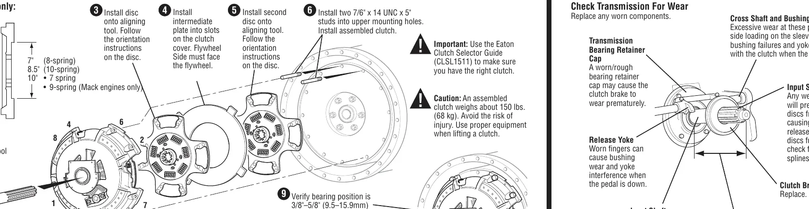
This guide covers the installation and setup of Eaton 14-inch and 15.5-inch heavy-duty manual adjust clutches. Proper installation is critical to prevent premature clutch wear and ensure vehicle safety. Always use the Eaton Clutch Selector Guide (CLSL1511) to verify you have the correct clutch for your application. Note that an assembled clutch weighs approximately 150 lbs (68 kg); use appropriate lifting equipment to avoid injury.
Measuring Flywheel and Housing
Before installation, the engine flywheel housing and flywheel must meet specific runout tolerances to prevent premature wear. Ensure all gauge contact surfaces are clean and dry. Use a dial indicator to check the following:
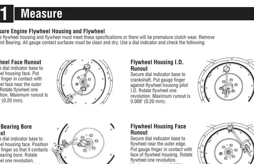
- Flywheel Face Runout: Maximum 0.008" (0.20 mm).
- Pilot Bearing Bore Runout: Maximum 0.005" (0.13 mm).
- Flywheel Housing I.D. Runout: Maximum 0.008" (0.20 mm).
- Flywheel Housing Face Runout: Maximum 0.008" (0.20 mm).
Clutch Setup and Lubrication
Proper bearing position and lubrication are essential for clutch longevity.
- Bearing Position: Measure the distance between the release bearing and the clutch brake. The correct distance is 0.500" – 0.560" (12.70 – 14.22 mm). If incorrect, adjust the clutch internally.
- Clutch Brake Squeeze: Insert a 0.010" (0.25 mm) feeler gauge between the release bearing and clutch brake. Press the pedal to clamp the gauge. If it does not clamp, adjust the linkage.
- Lubrication: Use Roadranger EP2 grease or an equivalent Lithium Complex, NLGI #2 or #3 grease with a dropping point temperature of 220°C (428°F) or higher. Apply grease to the input shaft, yoke, cross shaft bushings, and linkage pivot points. Grease the release bearing until it purges from the rear onto the input shaft.
Installing Clutch to Flywheel
The installation procedure varies slightly between 14-inch and 15.5-inch models. Always follow the orientation instructions provided on the discs. Use an aligning tool to ensure proper disc placement. For 15.5-inch clutches, install the intermediate plate and discs onto the aligning tool, then mount to the flywheel. For 14-inch clutches, ensure the flywheel depth is 2-15/16" before starting. Progressively tighten mounting bolts in a crisscross pattern to the specified torque (40–50 lbs. ft. for 14", 25–35 lbs. ft. for 15.5").
Installing Transmission
Ensure the transmission is in gear and the new clutch brake is installed. Position the transmission so it is square and aligned with the engine. Mesh the splines by moving the transmission forward and rotating the output shaft; do not use excessive force. Ensure yoke fingers remain in the up position until they are over the release bearing housing. Install mounting bolts and torque to OEM specifications.
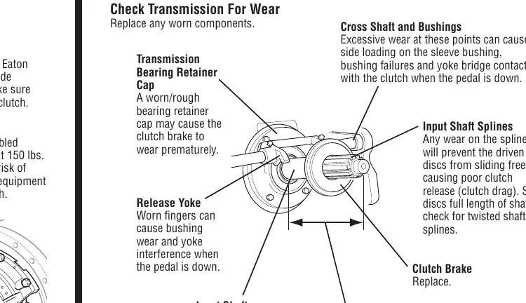
Transmission Wear Inspection
Before installing the transmission, inspect for wear:
- Input Shaft: Nominal length should be 8.657" (219.89 mm), not exceeding 8.71" (221.23 mm). Replace the bearing retainer cap if the length exceeds 8.71".
- Splines: Check for wear that prevents discs from sliding freely.
- Release Yoke: Check for worn fingers that cause bushing wear.
- Cross Shaft and Bushings: Check for excessive wear that causes side loading.
Manufacturer information
Eaton
Practical help
Common problems
Premature clutch wear
Ensure flywheel housing and flywheel meet runout specifications.
Poor clutch release (clutch drag)
Inspect input shaft splines for wear; ensure discs slide freely.
Side loading/bushing failure
Check cross shaft and bushings for excessive wear.
Before use
- Verify clutch compatibility using Eaton Clutch Selector Guide (CLSL1511).
- Ensure flywheel housing and flywheel meet runout tolerances.
- Clean and dry all gauge contact surfaces.
- Use proper lifting equipment (clutch weighs ~150 lbs / 68 kg).
- Ensure new clutch brake is installed before transmission mounting.
Specs in practice
- Flywheel Face Runout
- Maximum allowable runout is 0.008" (0.20 mm).
- Release Bearing Distance
- Distance between release bearing and clutch brake should be 0.500" – 0.560" (12.70 – 14.22 mm).
- Input Shaft Length
- Nominal 8.657" (219.89 mm); replace if greater than 8.71" (221.23 mm).
Images and diagrams
- Measuring flywheel runout using a dial indicator.
- Adjusting bearing position using the adjusting nut/lugs.
- Checking yoke finger and bearing wear pad clearance (1/8" / 3.2 mm).
Model compatibility
- Compatible with Eaton 14-inch and 15.5-inch heavy-duty manual adjust clutches.
- Requires specific Eaton Clutch Selector Guide (CLSL1511) for verification.

Manual page author
Emily Carter
User documentation editor
Prepares concise manual descriptions and highlights the most useful setup, operation, and maintenance information for readers.