Wearables / Smartwatches
Remote Intelligent Remote Control Switch 200A12VDC User Guide
Quick guide for the 200A12VDC Remote Intelligent Remote Control Switch. Learn how to install, wire, and pair your remote control with this step-by-step manual.
Quick answers from the manual
Quick answer
- The 200A12VDC is a remote-controlled battery switch for 12V systems. It supports up to 200A continuous current and requires careful wiring of relay pins 30, 87, 86, and 85 to function correctly. p. 1
Key actions
- Pairing the remote p. 1
- Clearing codes p. 1
First start
- Installation steps p. 1
Show 4 more answers Show less
Problems and fixes
Incorrect wiring
Ensure pin 86 is positive and pin 85 is negative to avoid burning the receiver module.
p. 1Maintenance and reset
- Clear all saved codes p. 1
Technical specifications
| Parameter | Value | Meaning | Pages |
|---|---|---|---|
| Voltage | 12V | Operating voltage | p. 1 |
| Continuous Current | 200A | Max load | p. 1 |
| Instant Current | 250A | Max surge | p. 1 |
Where to find it in the PDF
- Installation and Operation p. 1
- FCC Compliance p. 2
Table of contents
Quick guide from the manual
This device is a 12V remote-controlled switch designed for high-current applications. Before installation, ensure the power supply is disconnected. The device supports a continuous current of 200A and an instant start current of 250A. Do not use this device with 24V systems.
Installation instructions
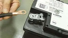
- Remove the negative electrode of the battery. If you need to control the positive electrode, remove the positive electrode wiring of the galvanic battery.
- Connect relay pin 30 to the negative terminal of the battery. If you need to control the positive terminal, connect relay pin 30 to the battery positive terminal.
- Remove the original battery bus to the switch's 87 pin.
- Connect the two thin wires on the switch to the battery terminals: the red wire to the positive pole (pin 86) and the black wire to the negative pole (pin 85).
Remote control matching
To pair the remote control with the switch:
- Press the button on the circuit board continuously for 3 seconds. The green work indicator light will flash three times, indicating the device has entered the learning code state.
- Press the ON button on the remote control. The green light will flash three times, then stay on.
- Press the OFF button on the remote control. The light will flash three times to confirm the code is matched.
- If no signal is received for 8 seconds, the device will automatically exit the matching state.
- To clear all saved codes, press the button on the circuit board 8 times in a row. The light will flash 8 times.
Safety notes
- Always turn off the power supply before performing installation operations.
- Do not operate with electricity connected.
- Ensure the working voltage is 12V; do not use with 24V systems.
- Do not overload the device beyond 200A continuous current.
- Ensure correct wiring of relay pins 85 and 86. Connecting them incorrectly can burn the internal receiver module.
Practical help
Common problems
Device does not work or receiver module burns out
Ensure relay pins 85 and 86 are connected correctly (86 is positive, 85 is negative). Incorrect polarity can damage the module.
Overload or overheating
Ensure the load does not exceed 200A continuous current or 250A instant start current.
Device not pairing
Ensure you are pressing the circuit board button for a full 3 seconds until the light flashes. If no signal is received for 8 seconds, the process times out.
Before use
- Verify the power supply is 12V (do not use 24V).
- Ensure the power supply is disconnected before starting installation.
- Identify relay pins 30, 87, 86, and 85.
- Prepare the battery terminals for disconnection.
Show more Show less
Specs in practice
- Working Voltage
- DC12V only.
- Continuous Current
- Maximum load capacity is 200A.
- Instant Start Current
- Maximum surge capacity is 250A.
Images and diagrams
- The installation images demonstrate the physical connection of the relay to the battery terminals.
- Images show the correct placement of the battery bus and the connection of the thin control wires to the relay pins.
Model compatibility
- Compatible with 12V battery systems only.
- Not compatible with 24V systems.

Manual page author
Michael Turner
Technical manual editor