Automotive / Electrical Accessories
Installation Guide for SSV Works 240-MBS3-SWE12 Alpha12 Switcher Box Mounting Kit
Step-by-step installation guide for the SSV Works 240-MBS3-SWE12 Alpha12 Switcher Box Mounting Kit designed for 2019+ Mercedes Benz Sprinter Vans. Includes tools required, assembly steps, and mounting instructions.
Quick answers from the manual
Quick answer
- This guide provides instructions for installing the SSV Works Alpha12 Switcher Box Mounting Kit into a 2019+ Mercedes Benz Sprinter Van. The process involves removing the overhead console, drilling mounting holes, assembling the bracket, and installing the controller. p. 3, 4, 5
Key actions
- Remove the overhead console using a plastic card. p. 3
- Drill 4 holes using a 6mm drill bit. p. 4
- Secure the controller to the mounting kit. p. 5
Where to find it in the PDF
- Parts Contents p. 2
- Installation Steps p. 3, 4, 5, 6
Table of contents
Manual images
Click an image to enlargeQuick Guide
This document provides instructions for installing the SSV Works Alpha12 Switcher Box Mounting Kit into a 2019+ Mercedes Benz Sprinter Van (Gen 3). Please read all instructions completely before beginning the installation to avoid injury or damage to the vehicle or accessory.
Tools Needed
- Plastic card
- Drill
- 6mm drill bit
- Small screwdriver
- Pick tool
- Phillips screwdriver
- 13mm wrench
Parts Contents
Ensure all parts are present before starting:
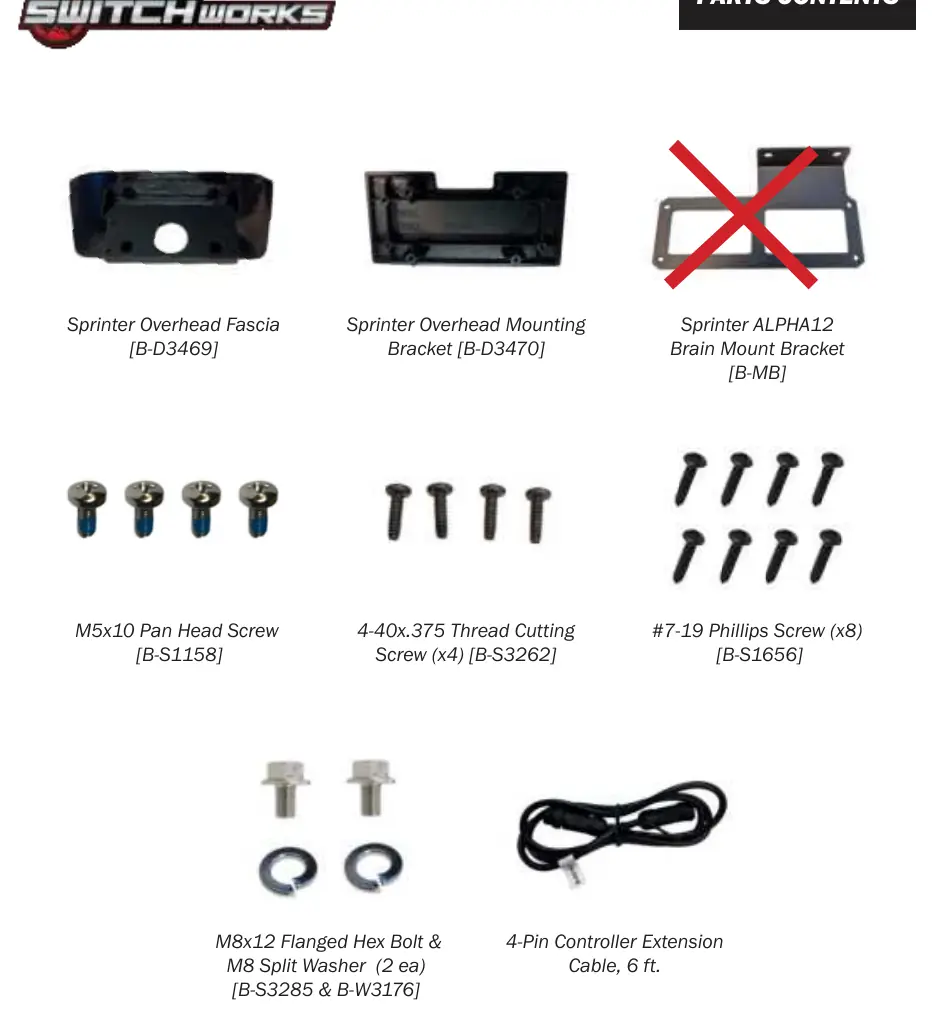
- Sprinter Overhead Fascia [B-D3469]
- Sprinter Overhead Mounting Bracket [B-D3470]
- Sprinter ALPHA12 Brain Mount Bracket [B-MB]
- M5x10 Pan Head Screw [B-S1158]
- 4-40x.375 Thread Cutting Screw (x4) [B-S3262]
- #7-19 Phillips Screw (x8) [B-S1656]
- M8x12 Flanged Hex Bolt & M8 Split Washer (2 ea) [B-S3285 & B-W3176]
- 4-Pin Controller Extension Cable, 6 ft.
Installation Steps
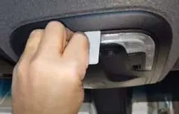

- Remove Console: Insert a plastic card into the middle front side of the overhead console to release the lock and slide it out.
- Disconnect: Unplug the connectors located behind the overhead console.
- Prepare Cavity: Unhook the two rubber limiter bands in the sunglass holder. Remove the plastic rotary damper by carefully pressing on the lock.
- Remove Holder: Use a small screwdriver to carefully pry out the sunglass holder from the overhead console.
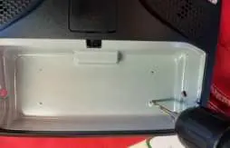
- Mark and Drill: Lay the Sprinter mounting bracket in the sunglass holder cavity. Use a pick tool to mark the screw hole locations. Use a marker to emphasize the points, then use a 6mm drill bit to drill 4 holes.
- Assemble: Join the Sprinter fascia and mounting bracket using four #7-19 screws (B-S1656).
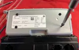
- Mount Controller: Line up the 15-button controller on the overhead mounting kit, paying attention to the orientation. Secure it using four 4-40x.375 Thread Cutting screws (B-S3262).
- Finalize: Insert the controller cable through the plastic rotary damper hole. Hold the mounting bracket in the sunglass holder cavity and fasten the back side with the remaining #7-19 screws.
Warranty Information
All SSV Works non-electronic parts are covered by a limited lifetime warranty against defects in material or workmanship. All SSV Works electronics are covered by a limited 1-year warranty. Labor for replacement of defective components is not covered.
Practical help
Common problems
Difficulty removing the overhead console
Ensure you are using a plastic card to gently release the locking mechanism at the middle front side of the console.
Controller orientation issues
Pay close attention to the orientation of the 15-button controller relative to the overhead mounting kit before securing it with screws.
Before use
- Verify vehicle compatibility (2019+ Mercedes Benz Sprinter Van Gen 3)
- Gather all required tools: Plastic card, drill, 6mm bit, screwdrivers, pick tool, 13mm wrench
- Read all safety warnings in the manual before starting
- Check that all parts listed in the 'Parts Contents' section are present
Show more Show less
Specs in practice
- 4-Pin Controller Extension Cable
- Included cable length is 6 feet.
- Drill Bit Size
- Use a 6mm drill bit for the mounting holes.
Images and diagrams
- Steps A-D: Removing the overhead console and sunglass holder components.
- Steps E-H: Marking and drilling the mounting holes in the console cavity.
- Steps I-M: Assembling the fascia, bracket, and controller, and routing the cable.
Model compatibility
- Designed specifically for 2019-Up Mercedes Benz Sprinter Van (Gen 3).

Manual page author
Michael Turner
Technical manual editor