Lighting / Controllers Dimmers
EcoDim Eco-Dim.05 Zigbee Smart Dual Dimmer Switch User Guide
Quick guide for the EcoDim Eco-Dim.05 Zigbee Smart Dual Dimmer Switch. Includes installation, wiring, MIN/MAX adjustment, and Zigbee pairing instructions.
Table of contents
Quick guide from the manual
This document provides instructions for the EcoDim Eco-Dim.05 Zigbee Smart Dual Dimmer Switch. The device is designed for 2x0-100W LED lighting and supports Zigbee connectivity. Key operations include installation, MIN/MAX light level calibration, and various Zigbee network pairing modes.
Product Overview
The Eco-Dim.05 Zigbee is a dual dimmer switch featuring:
- Zigbee support for both channels.
- Voice support (Amazon Alexa & Google Assistant/Home).
- Overload and overheating protection.
- No neutral wire required for installation.
- Compatible with various cover material brands (e.g., Berker, Busch-Jaeger, Gira, JUNG, Kopp, Merten, PEHA).
Installation
Warning: Always ensure the electricity is switched off during installation.
- Ensure the power supply is disconnected.
- Connect the wires as indicated in the connection diagram.
- Install the dimmer in the mounting box using the screws.
- Switch the electricity back on.
- Switch on the connected lights by pressing the dimmer shaft.
- Perform MIN/MAX adjustment if necessary.
- Place back the cover plate and dimmer knob.
MIN/MAX Adjustment
To ensure optimal performance, you can adjust the minimum and maximum light levels:
- MIN adjustment: Switch on the lights. Insert a screwdriver into the MIN slot and turn to the left. If the light becomes unsteady, turn slightly back to the right until the light remains steady.
- MAX adjustment: Switch on the lights. Insert a screwdriver into the MAX slot and turn to the right. If the light becomes unsteady, turn slightly back to the left until the light remains steady.
Zigbee Network Operations
The device uses the reset button for various network functions:
- Factory Reset: Press and hold the reset button for at least 5 seconds. The indicator will stay red for 10 seconds when complete.
- Include to Zigbee Network: Remove the device from any previous network first. Press the reset button twice. The indicator starts blinking blue and stays solid for 10 seconds upon success.
- Remove from Network: There are two methods. Method 1: Use your Zigbee Hub interface. Method 2: Press the reset button three times. The indicator will blink purple and stay on for 10 seconds.
- TouchLink (Right channel only): Press the reset button 4 times. The indicator will blink green and stay solid for 10 seconds. Bring the remote within 10cm of the dimmer.
- Find and Bind: Turn the left channel on, then press the reset button 5 times within 10 seconds. The indicator will blink yellow and stay solid for 10 seconds.
Technical Specifications
- Input voltage: 220-240V~ 50Hz
- Load: 2x100W LED / 2x10-100W Halogen/Incandescent
- Dimming type: R,C Phase cut
- Working temperature: -10-40°C
- Operation: Push/Turn button
- Weight: 83g
Manufacturer information
EcoDim B.V.
Practical help
Common problems
Pairing fails
Ensure the device is removed from any previous Zigbee network before attempting to pair.
Light instability
Adjust the MIN or MAX settings using a screwdriver until the light remains steady.
TouchLink not working
Ensure both devices have not been added to a Zigbee network yet and are within 10cm of each other.
Before use
- Ensure electricity is switched off at the mains.
- Verify that the load type is compatible (LED, Halogen, Incandescent).
- Have a screwdriver ready for MIN/MAX adjustments.
- Check that the mounting box is suitable for the dimmer dimensions.
Specs in practice
- 220-240V~ 50Hz
- Standard mains voltage and frequency for the device.
- R,C Phase cut
- The dimming technology used, suitable for most LED and halogen lamps.
Images and diagrams
- The wiring diagram shows the connection of Live (L) and Neutral (N) lines to the dimmer and the two light circuits.
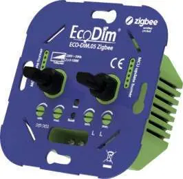
- The front panel diagram identifies the MIN/MAX adjustment slots, the reset button, and the LED indicator.
Model compatibility
- Compatible with cover materials from: Berker by Hager, Busch-Jaeger, Gira, JUNG, Kopp, Merten by Schneider, PEHA.

Manual page author
Emily Carter
User documentation editor
Prepares concise manual descriptions and highlights the most useful setup, operation, and maintenance information for readers.