HVAC / Heaters & Fireplaces
Installation Guide for EGO Airmatic 8 M3 Core and Comfort Airmatic 10 M3 Core Pellet Stoves
Comprehensive installation and setup guide for EGO Airmatic 8 M3 Core and Comfort Airmatic 10 M3 Core pellet stoves. Includes safety warnings, technical specifications, assembly instructions, and maintenance requirements.
Table of contents
Manual images
Click an image to enlargeImportant Information from the Manual
This installation guide is intended for qualified operators. It covers the installation, assembly, and technical specifications for the EGO Airmatic 8 M3 Core and EGO Comfort Airmatic 10 M3 Core pellet stoves. Always comply with local regulations and national standards when installing the appliance. The manufacturer is not liable for damage caused by improper installation or maintenance.
Safety Warnings
- Qualified Operator: Installation, electrical connection, and maintenance must be performed by a qualified operator.
- Fuel: Use only EN ISO 17225-2 class A1 certified wood pellets. Do not use other fuels or liquids.
- Surfaces: Many surfaces become very hot during operation. Use protective equipment like thermal gloves.
- Electrical: Connect to a properly earthed 230V system. Disconnect before maintenance.
- Ventilation: Ensure the room has adequate air supply and smoke outlets.
- Prohibitions: Do not dry laundry on the stove, do not operate with the door open, and do not use the stove as an incinerator.
Installation Requirements
The stove must be installed in a room with adequate air supply. A sealed installation is recommended for high-efficiency homes. Ensure the floor can support the weight of the appliance (130-133 kg). Maintain minimum safety distances from flammable materials as specified in the technical data.
Assembly Instructions
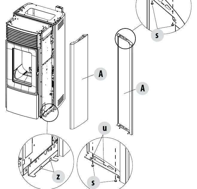
The stove is delivered with the top fitted but without metal side cladding. Follow these steps for assembly:
- Unpacking: Remove packaging, cardboard, and polystyrene. Handle the stove body in a vertical position.
- Removing the Top: Lift the pellet cover, remove the screws under the cover, and remove the top panel.
- Fitting Side Panels: Attach silicone bumpers to the panels. Insert the bottom holes of the panel onto the structure hooks. Secure the panels with screws and notched washers.
- Refitting the Top: Once cladding is installed, replace the top panel and secure it with the previously removed screws.
Operation and Maintenance
Loading Pellets: Lift the upper door to pour pellets into the hopper. Do not pour pellets directly into the brazier. Always keep the hopper cover closed.
Door Opening: Use the provided cold handle to open the firebox door. Open the firebox door before attempting to open the lower door.
Maintenance: Yearly maintenance by a qualified operator is mandatory. Keep the brazier clean and remove unburnt pellets after any failed ignition.
Technical Specifications
Refer to the technical specifications tables in the manual for detailed data on nominal power (8.0 kW for 8 M3, 10.0 kW for 10 M3), efficiency, exhaust temperatures, and fuel consumption. Ensure the chimney is sized correctly according to EN 13884-1.
Practical help
Common problems
Stove not powering on
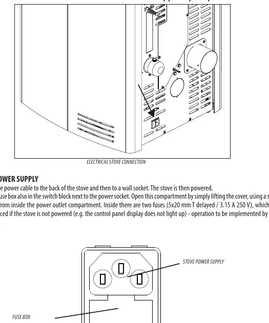
Check the fuse box next to the power socket. Replace fuses (5x20 mm T delayed / 3.15 A 250 V) if necessary; this must be done by a qualified technician.
Smoke emission on first start
This is normal due to the paint heating up for the first time. Ensure the room is well-ventilated.
Failed ignition
Accumulated unburnt pellets in the brazier must be completely removed before attempting to light the stove again.
Before use
- Ensure installation is performed by a qualified operator.
- Verify the room has an adequate external air inlet (min 80 cm2).
- Check that the smoke duct complies with EN 13884-1.
- Ensure the floor is made of non-combustible material or use a floor guard.
- Use only EN ISO 17225-2 class A1 certified wood pellets.
- Verify the stove is level using the 4 adjustable feet.
Specs in practice
- Nominal Output Power
- 8.0 kW for EGO Airmatic 8 M3 Core; 10.0 kW for EGO Comfort Airmatic 10 M3 Core.
- Hopper Capacity
- 39 litres, sufficient for the specified autonomy.
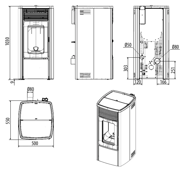
- Smoke Outlet
- 80 mm diameter connection required for the flue.
- Combustion Air Inlet
- 50 mm diameter connection for external air supply.
Images and diagrams
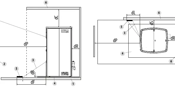
- Minimum distances diagram (p. 15) illustrates required clearances from flammable materials (e.g., 40-120 mm rear, 100-200 mm side).
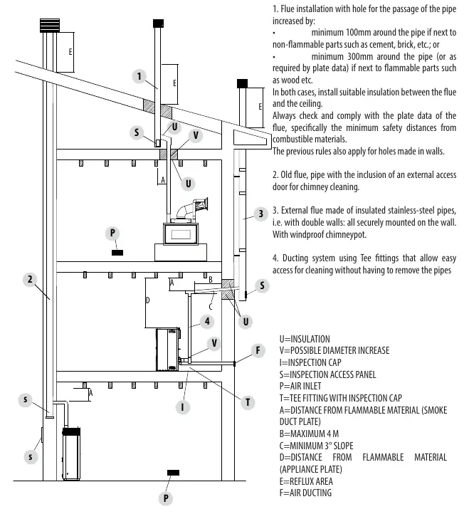
- Installation examples (p. 20) show correct flue and air ducting configurations.
- Electrical connection diagram (p. 42) shows the location of the power socket and fuse box.
Model compatibility
- Requires EN ISO 17225-2 class A1 certified wood pellets (6 mm diameter, 3-40 mm length).
- Not for use with liquid fuels or as an incinerator.
- Must be connected to a properly earthed 230V/50Hz power supply.

Manual page author
Michael Turner
Technical manual editor
Reviews PDF manuals for structure, safety notes, and practical product details so readers can find the right information quickly.