Power / Portable Power Stations
Global Industrial 246102 Horizontal Unit Heater
Quick guide for the Global Industrial 246102 Horizontal Unit Heater. Includes installation instructions, wiring diagrams for 1 or 3-phase connections, thermostat settings, and troubleshooting steps.
Table of contents
Manual images
Click an image to enlargeQuick guide from the manual
This manual provides essential instructions for the installation, operation, and maintenance of the Global Industrial 246102 Horizontal Unit Heater. This unit is designed for commercial/industrial use and must not be used as a residential or household heater. Installation must be performed by a certified electrician in accordance with local codes.
Product Description and Specifications
The 246102 is a 10KW, 240V horizontal unit heater capable of operating on either 1 or 3-phase power. It features a cold-rolled steel construction, built-in thermal cut-off protection, and options for either a built-in or external wall thermostat.
- Voltage: 240V
- Power: 10,000 Watts (10KW)
- Phase: 1 or 3 Phase
- Circuit Breaker: 60A
- Wire Size: 6 AWG copper
- Airflow: 600 CFM
Installation Instructions
Proper installation is critical for safety and performance. Ensure the following clearances are maintained:
- Height: Minimum 6 feet (1.8 m) from the floor.
- Side/Rear: Minimum 1 foot (0.3 m) from adjacent vertical surfaces or walls.
- Back Wall: Minimum 4.5 inches (11.5 cm) from the back wall.
- Front/Top: Keep combustible materials at least 3 feet (0.9 m) away.
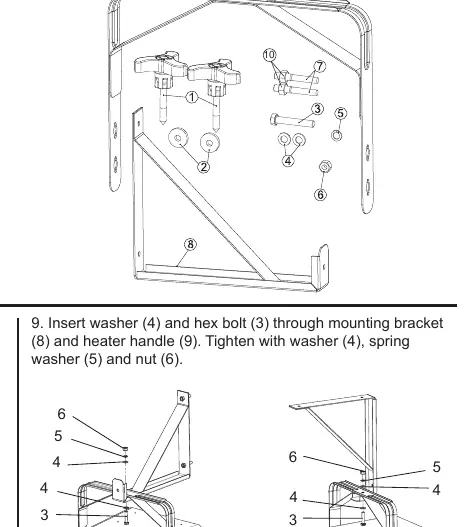
Mounting Steps:
- Mark hole locations on the wall or ceiling.
- Drill two holes using a 0.48 inch (12mm) drill bit, 2.75 inches deep.
- Insert expansion bolts (7) flush to the surface.
- Attach the mounting bracket (8) and secure with expansion nuts (10).
- Hook the unit onto the mounting bracket.
- Secure the unit using the hex bolt (3), washers (4), spring washer (5), and nut (6).
Wiring Connections
Important: Disconnect the main power supply before starting any wiring work. Use 6 AWG copper wires.
Single Phase Connection
- Open the wiring access window.
- Connect the two supply cords to terminals L1 and L3.
- Replace the cover and secure with the screw.
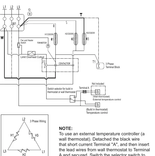
3 Phase Connection
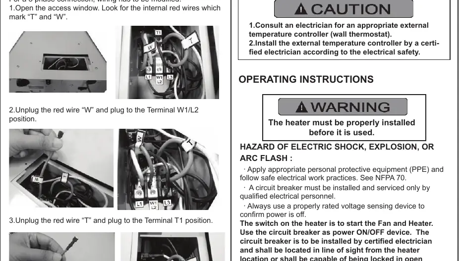
- Open the wiring access window.
- Locate the internal red wires marked 'T' and 'W'.
- Unplug the red wire 'W' and connect it to the Terminal W1/L2 position.
- Unplug the red wire 'T' and connect it to the Terminal T1 position.
- Connect the supply cords to L1, L2, and L3.
- Replace the cover and secure with the screw.
Operating Instructions
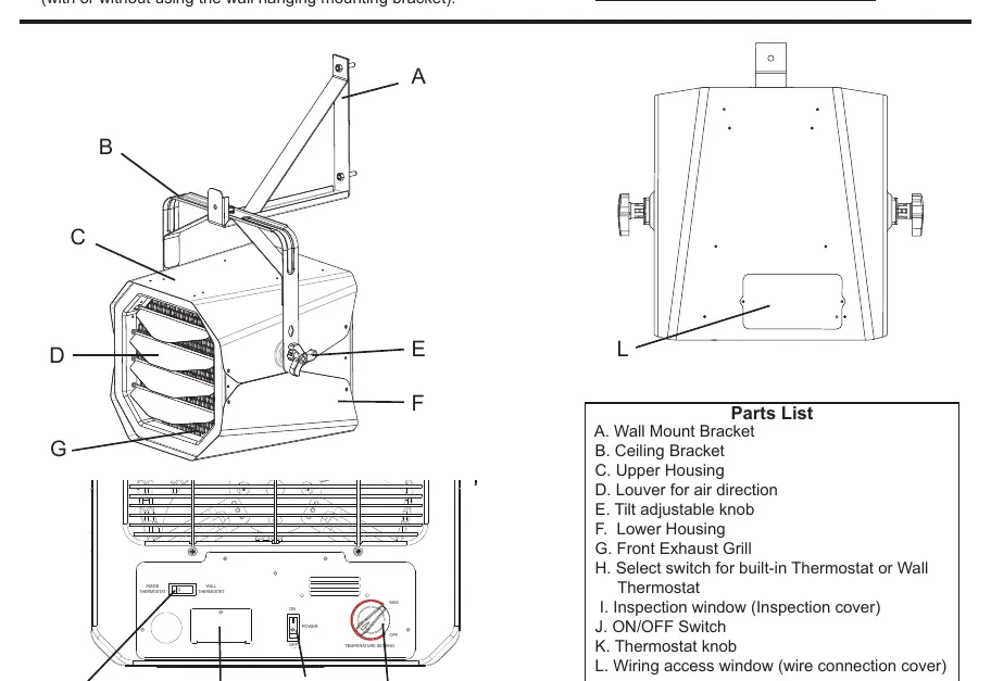
The heater can be controlled via the built-in thermostat or an external wall thermostat.
- Selector Switch: Set to 'INSIDE THERMOSTAT' for the built-in control or 'WALL THERMOSTAT' for an external controller.
- Operation: Use the circuit breaker as the main power ON/OFF device. Use the switch on the back of the heater to turn the fan and heating function on or off.
- Temperature Adjustment: Turn the thermostat knob clockwise to increase the temperature or counterclockwise to decrease it.
Maintenance and Cleaning
The unit requires minimal maintenance. Before cleaning, disconnect the power supply and wait 60 minutes for the heating element to cool.
- Cleaning: Do not use liquid chemicals. Use a vacuum cleaner with a crevice tool to remove interior dust. Wipe the enclosure with a clean, soft, lightly damp cloth.
- Caution: Do not allow water to enter the interior of the heater.
Troubleshooting
If the heater fails to operate, check the following:
- Unit not heating: The thermal cut-off protection may have tripped. Turn off the power at the circuit breaker, wait 10 minutes for it to reset, and then turn it back on. Also, check if the circuit breaker has tripped.
- Burning smell: This is normal during the first use due to oil on the heating coil from manufacturing. Ensure the room is well-ventilated.
Practical help
Common problems
Unit is not heating
Check if the thermal cut-off has tripped (wait 10 minutes) or if the circuit breaker has tripped.
Burning smell during initial use
This is normal; oil on the heating coil is evaporating. Ensure the room is well-ventilated.
Before use
- Ensure installation height is at least 6 feet (1.8 m) from the floor.
- Verify 1 foot (0.3 m) clearance from adjacent walls.
- Verify 4.5 inches (11.5 cm) clearance from the back wall.
- Ensure 60A circuit breaker is installed.
- Use 6 AWG copper supply wires.
- Confirm power source phase (1 or 3) matches wiring configuration.
Specs in practice
- 1 or 3 Phase
- The heater supports both single-phase and three-phase electrical systems with specific wiring modifications.
Images and diagrams
- Wiring diagram shows connections for 1-phase (L1, L3) and 3-phase (L1, L2, L3) configurations.
- Installation diagram illustrates the wall bracket assembly and unit mounting process.
Model compatibility
- Not for residential or household use.
- Must be installed by a certified electrician.
- Requires specific wiring modification for 3-phase operation.

Manual page author
Michael Turner
Technical manual editor
Reviews PDF manuals for structure, safety notes, and practical product details so readers can find the right information quickly.