HVAC / Heaters & Fireplaces
Installation Manual for Sterling DURA-VANE II Commercial Finned Tube Radiation
A comprehensive installation and maintenance guide for the Sterling DURA-VANE II Commercial Finned Tube Radiation (JDVA/JDVB 10LI). Includes step-by-step mounting instructions, hanger spacing requirements, and maintenance tips.
Table of contents
Quick Guide for Installation
The Sterling DURA-VANE II is a commercial finned tube radiation system. Proper installation requires adherence to specific hanger spacing and system-specific requirements. For copper tube elements, it is critical to flush the system after soldering to prevent corrosion. Maintenance involves regular cleaning of the fins to ensure proper airflow.
Installation Steps
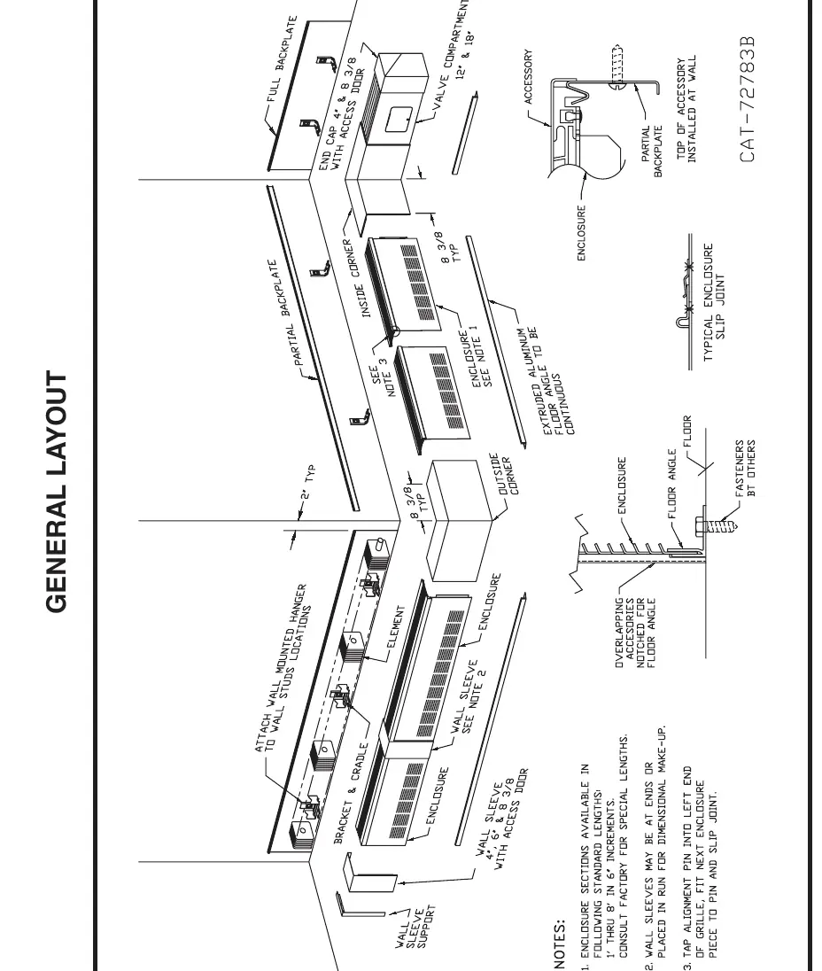
- Preparation: Determine the required quantities of enclosure and accessories. If installing wall-to-wall, run the backplate to within 1/2 inch of the adjoining wall. If ending with an end cap, extend the backplate 1-1/2 inches for a 4-inch end or 6 inches for an 8-3/8 inch end.
- Mounting Backplate: Mount the backplate (full or partial) at the prescribed height as shown in the submittal drawing. Ensure it is straight and level.
- Floor Angle: Install the extruded aluminum floor angle to the floor at the location shown on the submittal drawing. This should run the full length of the installation.
- Hanger Installation: For hot water or two-pipe steam systems, install wall-mounted hangers to support the element. Use two hangers per element length up to 6 feet, and three hangers for lengths between 6 feet 6 inches and 12 feet 6 inches. For steam systems, ensure the supply end is at the highest point and pitches down at 1/2 inch per 20 feet.
- Heating Element: Place the slide cradle on the bottom of the element at each bracket location. Position the cradle legs between the fins to create tension. Check the submittal drawing for the correct fin position.
- Enclosure Installation: Start at the left end and work clockwise. Tap the alignment pin into the left front end of the grille. Engage the rear of the grille into the V-bend of the backplate. Push the next piece of cover into the slip joint tabs and alignment pin. Secure the bottom into brackets and tighten the posi-loc clamps.
- Accessories: Install overlapping accessories as indicated on the room schedule.
Maintenance
Before each heating season, remove the accessories and enclosure panel to inspect the finned tube elements. Accumulation of dust or debris can block airflow between the fins. Remove any debris using a vacuum cleaner or compressed air. Inspect the system for leaks or areas of corrosion. If applicable, apply a drop of machine oil to ball bearings located in water brackets or bracket-mounted hangers.
Practical help
Common problems
Pinhole leaks in copper elements
Flush the loop or series with system water after soldering to neutralize remaining flux material.
Airflow blockage
Remove dust and debris from coil fins using a vacuum cleaner or compressed air.
Before use
- Ensure backplate is straight and level.
- Verify hanger spacing requirements based on element length.
- Check submittal drawing for correct element fin position.
- Flush copper tube elements after soldering.
- Inspect for leaks or corrosion before the heating season.
Specs in practice
- Hanger spacing (up to 6'-0")
- Requires 2 wall mounted hangers.
- Hanger spacing (6'-6" to 12'-6")
- Requires 3 wall mounted hangers.
- Steam system pitch
- Supply end must start at the highest point and pitch down at 1/2 inch per 20 foot run.
Images and diagrams
- The General Layout diagram illustrates the assembly sequence of the backplate, floor angle, hangers, heating element, and enclosure.
Model compatibility
- Compatible with hot water and two-pipe steam systems.

Manual page author
Emily Carter
User documentation editor
Prepares concise manual descriptions and highlights the most useful setup, operation, and maintenance information for readers.