Smart Home / Hubs & Controllers
Quick Start Guide for Emerson Wireless 1410 A/B and 1410D Gateway
Quick start guide for the Emerson Wireless 1410 A/B and 1410D Gateway. Includes installation, wiring, configuration, and setup instructions.
Table of contents
Manual images
Click an image to enlargeQuick guide from the manual
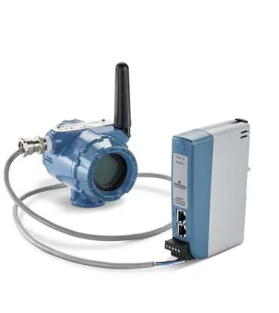
This guide provides essential steps for the initial setup and installation of the Emerson Wireless 1410 A/B and 1410D Gateways. Before beginning, ensure you have a PC with a supported web browser and an Ethernet cable. The Gateway is configured via a web interface at https://192.168.1.10. For hazardous area installations, ensure all I.S. barriers are installed according to the specific requirements outlined in the manual.
Wireless planning
For optimal network performance, install the Gateway and ensure it is functioning before powering on wireless field devices. Power up field devices in order of proximity to the Gateway, starting with the closest. The antenna should be positioned vertically, approximately 6 ft (2 m) from large structures. For remote antennas, the ideal mounting height is 15–25 ft (4.6–7.6 m) above ground or 6 ft (2 m) above major obstructions.
PC requirements
Configuration requires a PC running a supported operating system, including Windows Server 2008, Windows 7, 8, or 10. Supported browsers include Internet Explorer, Chrome, Mozilla Firefox, and Microsoft Edge. Ensure at least 1.5 GB of hard disk space is available for the AMS Wireless Configurator.
Initial connection and configuration
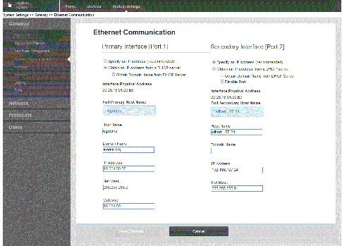
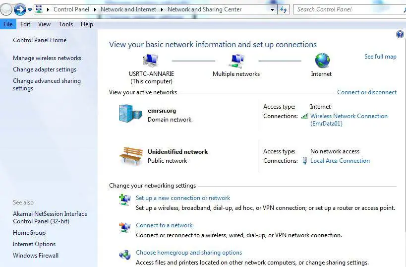
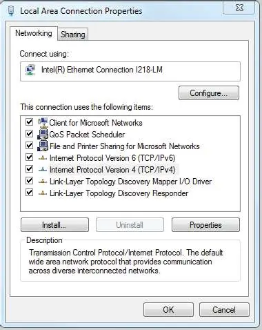
To configure the Gateway, establish a local connection between your PC and the Gateway's Ethernet 1 port. Note: Record your PC's current network settings before changing them to allow for restoration later. Set your PC's IP address to 192.168.1.12 and Subnet mask to 255.255.255.0. Access the web interface at https://192.168.1.10 using the username admin and password default. Navigate to System Settings > Gateway > Ethernet Communication to configure static IP or DHCP settings.
Physical installation
The unit is designed for mounting on a DIN TS35/7.5 or TS35/15 rail system. To install, tilt the unit to catch the lower lip of the chassis on the bottom of the DIN rail, then apply forward pressure to snap the back of the unit securely into place. To remove, insert a flat object into the DIN clip, apply downward pressure, and pull the unit backwards and down.
Wiring and grounding
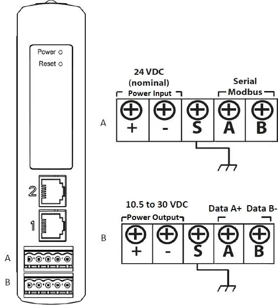
The 1410D model requires specific wiring when connected to the 781 Field Link. Use shielded twisted pair cable (Belden 3084A or equivalent). For installations in hazardous areas, power and signal barriers are required. Ensure the DIN rail cabinet is grounded using a #6 AWG copper wire with the shortest possible length, avoiding sharp bends or coiling.
Remote antenna installation
Use only Emerson-provided remote antennas, coaxial RF cables, and lightning arrestors. Mount the antenna on a 1.5 to 2-inch pipe mast. Ensure the lightning arrestor is grounded to a common earth point. All outdoor connections must be hand-tightened plus an 1/8th turn with a wrench and sealed with the provided coaxial sealant to prevent weather damage.
Software installation
Optional software, including the Security Setup Utility and AMS Wireless Configurator, is provided on a 2-disk pack. Close all running Windows programs before inserting the disk. If the setup does not start automatically, run autorun.exe from the disk.
Verify operations
Once configured, verify operation by entering the Gateway's IP address or host name into a web browser. A successful connection will display a security alert followed by the login screen. The Gateway is then ready for integration into the host system.
Official resources from the manual
Practical help
Common problems
Cannot connect to the web interface
Verify the Ethernet cable is connected to Port 1, ensure the PC IP address is set to 192.168.1.12, and disable any active proxy servers in your browser settings.
Gateway not communicating with field devices
Ensure the Gateway is fully powered and configured before powering on field devices. Power up field devices in order of proximity to the Gateway.
Before use
- Verify power source is 10.5–30 VDC (at least 250 mA).
- Ensure PC has a supported browser (Chrome, Firefox, Edge, IE).
- Record current PC network settings before changing IP address.
- Ensure DIN rail is available for mounting.
- Verify if hazardous area installation requires I.S. barriers.
Specs in practice
- 250 Ohm Resistor
- Terminating resistor required for serial communication; enabled by shorting specific terminals.
Images and diagrams
- Figure 1/2: Shows power and serial terminal layout for 1410A/B and 1410D.
- Figure 7/8: Illustrates DIN rail mounting and removal procedure.
- Figure 9/10/11: Wiring diagrams for 1410D and 781 Field Link with and without barriers.
Model compatibility
- 1410A/B and 1410D are operationally equivalent for configuration.
- Requires specific I.S. barriers for hazardous area installations.

Manual page author
Emily Carter
User documentation editor
Prepares concise manual descriptions and highlights the most useful setup, operation, and maintenance information for readers.