Industrial / Communication Modules
User Manual for Emerson Wireless 1410S Gateway
Quick start guide for the Emerson Wireless 1410S Gateway. Includes installation, wiring, network configuration, and safety instructions for 1410S1 and 1410S2 models.
Table of contents
Manual images
Click an image to enlargeImportant Information
This guide provides basic guidelines for the Emerson Wireless 1410S Gateway. It does not provide instructions for diagnostics, maintenance, service, or troubleshooting. Refer to the Emerson Wireless Gateway 1410S Reference Manual for more information.
Safety Warnings
- Explosion Hazard: Do not make or break any connections to the gateway while circuits are live unless the area is known to be non-hazardous.
- Electrostatic Hazard: The enclosure's polyurethane paint finish (1410S2) or polymeric enclosure (1410S1) may constitute an electrostatic hazard. Use care in handling and cleaning in explosive environments.
- Physical Access: Restrict physical access to unauthorized personnel to prevent damage or misconfiguration.
Wireless Planning
The gateway should be installed and functioning properly before power modules are installed in any wireless field devices. Wireless field devices should be powered up in order of proximity from the gateway, beginning with the closest.
PC Requirements
- Operating System: Microsoft Windows Server 2019 (Standard Edition) or Windows 10 Enterprise.
- Browsers: Chrome, Mozilla Firefox, or Microsoft Edge.
- Disk Space: 1.5 GB for AMS Wireless Configurator; 250 MB for Gateway Setup CD.
Initial Connection and Configuration
To configure the gateway, a local connection between a computer and the gateway is required.
- Powering: The gateway requires a 10.5–30 VDC power source or Power over Ethernet (PoE) compliant with IEEE 802.3af.
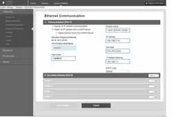
- Default IP Addresses: Ethernet port 1 is 192.168.1.10; Ethernet port 2 is 192.168.2.10.
- Login: Access the web interface at https://192.168.1.10. Use username admin and password default. Change the password immediately after the initial sign-in.
Physical Installation
1410S1 DIN-rail mounting: Snap the gateway onto a DIN TS35/7.5 or TS35/15 rail system. Press the upper release tab to secure or remove the unit.
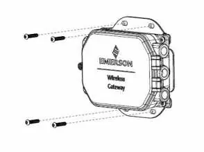
1410S2 Pipe/Surface mounting: Use the supplied mounting plate. For pipe mounting, use two 5/16-in. u-bolt kits on a 2-in. pipe. For surface mounting, use four appropriate fasteners.
Wiring
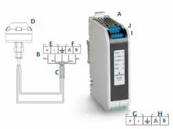
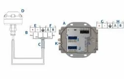
Ensure the cable is rated for the ambient temperature of the installation. Strip insulation back a minimum of 0.14 inches. Connect positive and negative wires to the appropriate terminals. For 781S antenna connections, use shielded, twisted pair cable (e.g., Belden 3084A). The maximum cable length between the 1410S and 781S is 400 m (1312 ft).
Grounding
1410S1: Grounded through the DIN-rail mounting plate. Ensure proper contact with the DIN-rail.
1410S2: Ground the enclosure case using internal or external grounding provisions. Use a conductor larger than 11AWG. The connection should be 1 ohm or less.
Verify Operations
Verify operation via the web interface. Ensure field devices have the correct Network ID and Join Key. Confirm that field devices are joined to the network and that the host system is receiving data.
Practical help
Common problems
Cannot access web interface
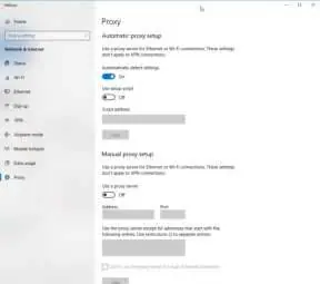
Ensure PC is on the same subnet (192.168.1.x) and connected to Ethernet 1.
Lost password
Requires factory reset, which clears all user settings.
Antenna issues
Do not mount the antenna inside a metal enclosure.
Before use
- Verify power source (10.5-30 VDC or PoE).
- Ensure PC browser is Chrome, Firefox, or Edge.
- Identify model: 1410S1 (DIN-rail) or 1410S2 (Pipe/Surface).
- Have Ethernet cable ready for initial configuration.
Specs in practice
- 192.168.1.10
- Default IP address for Ethernet port 1.
- 192.168.2.10
- Default IP address for Ethernet port 2.
Images and diagrams
- Wiring diagrams show power input, serial Modbus, and antenna connections.
- Mounting diagrams illustrate DIN-rail (1410S1) and pipe/surface (1410S2) installation.
Model compatibility
- 1410S1 requires external IP54 enclosure.
- 1410S2 hardware revision 1.0.0 with Intrinsically Safe Outputs option A requires 24 VDC power.

Manual page author
Emily Carter
User documentation editor
Prepares concise manual descriptions and highlights the most useful setup, operation, and maintenance information for readers.