Lighting / Controllers Dimmers
Installation Manual for Encelium 0-10V Connected Lighting Module
Comprehensive installation and configuration guide for the Encelium 0-10V Connected Lighting Module. Includes mounting, wiring, testing, and reset procedures.
Table of contents
Quick guide from the manual
The Encelium Connected Lighting Module (CLM) is a wireless device designed for individual luminaire control. Key installation steps include mounting the module in a NEMA PG-7 knockout, wiring using 18-22 AWG wire, and performing the automatic End-of-Line (EOL) functional test upon power-up. Ensure the LED driver has 'dim-to-off' enabled for proper operation.
Product Overview
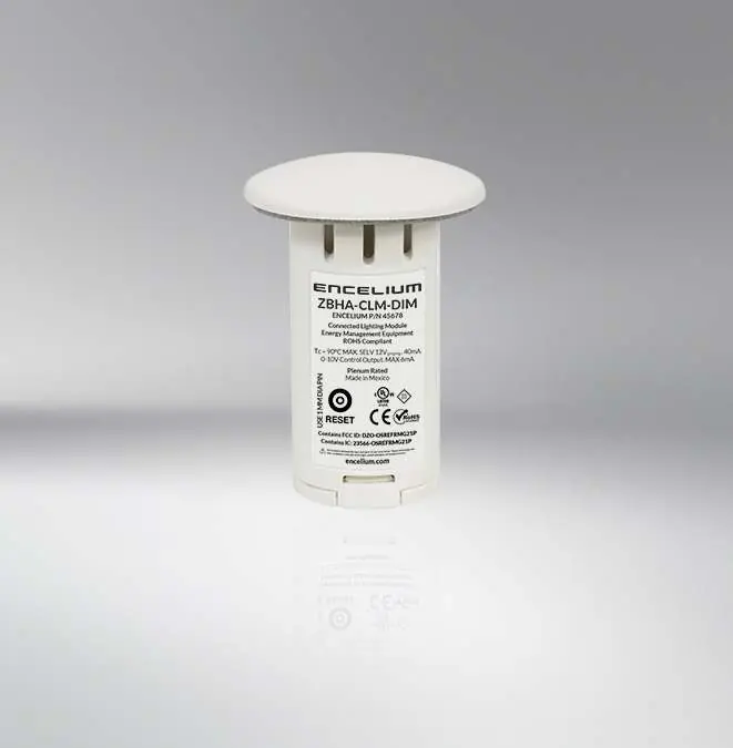
The CLM is a wireless control module that integrates into the Encelium X Lighting Control System. It is designed to reduce electrical contractor labor hours during on-site installation by providing a simple, wireless interface for luminaire control.
Safety Precautions
- Do not mount the device near gas or electric heaters.
- Ensure power supply cords do not touch hot surfaces.
- Mount the device in locations and at heights where it is not easily accessible to unauthorized personnel.
- Do not use accessory equipment not recommended by Encelium.
- Note that all DALI channels are internally connected to the control unit.
- Do not use the equipment for purposes other than its intended use.
Installation
Mounting: The CLM is designed to be mounted in a luminaire or mounting plate through a NEMA standard PG-7 (0.5 inch) trade size knockout. The opening diameter must be between 21.82 mm and 23.01 mm (0.85 to 0.9 inches). The attached mounting clips will hold the unit in place. Do not wire the CLM before installing it in the knockout, as space will be insufficient.
Wiring: Use wire between 18-22 AWG with a maximum total diameter of 2.23 mm (0.09 inch). Strip the wire to a length of 7 mm (0.3 inch). Insert the wires through the terminals and push until the insulation passes through the CLM body and hits the inside layer of the assembly. This ensures the wires engage correctly in the terminal blocks.
Electrical Connections
The module supports various wiring configurations, including 0-10V LED drivers and DALI/DEXAL/Tunable White LED drivers. Ensure the LED driver has 'dim-to-off' enabled. If all drivers are non-auxiliary, an external power supply may be required. Use the built-in strain relief or a zip tie to ensure a reliable connection.
Testing and Commissioning
Upon power-up, the CLM automatically performs an End-of-Line (EOL) functional test (for the first 10 power-ups). The luminaire will cycle from 100% to Off 2 to 3 times, confirming power and communication. If connected to a Tunable White driver, the luminaire will cycle through color temperatures (cool white, warm white, default) after the blinking sequence. The Wiring Test Tool (EN-WTT-ZB) can be used to initiate a test sequence prior to commissioning.
Maintenance and Resetting
Rewiring: The CLM can be rewired a maximum of 2 times. To rewire, cut the wires leaving 25.4 to 50.8 mm (1 to 2 inches), then carefully rotate the wire while pulling backwards to remove. Repeated attempts beyond the limit can permanently damage the terminals.
Resetting: To reset the product to factory default settings, press the reset button for 5 seconds while the device is powered. This removes group membership, binding tables, and resets persistent attributes.
Practical help
Common problems
Insufficient connection in terminals
Ensure wire thickness is 18-22 AWG and strip length is exactly 7 mm. Push wire until insulation hits the inside layer of the CLM assembly.
Cannot install unit in knockout
Do not wire the CLM before installing it in the knockout; the space is insufficient for pre-wired installation.
Rewiring failure
The CLM can only be rewired a maximum of 2 times. Repeated attempts will damage the terminals.
Before use
- Verify knockout size is NEMA PG-7 (21.82 to 23.01 mm).
- Use 18-22 AWG wire.
- Strip wire insulation to 7 mm.
- Ensure LED driver has 'dim-to-off' enabled.
- Ensure device is powered during reset procedure.
Specs in practice
- Knockout Size
- NEMA PG-7 (0.5 inch) trade size, 21.82-23.01 mm diameter.
- Rewiring Limit
- Maximum of 2 times before terminal strength is compromised.
Images and diagrams
- Mounting: Shows insertion into knockout and locking mechanism.
- Wiring: Details strip length (7mm) and terminal insertion depth.
- 0-10V Wiring: Illustrates connection between CLM, LED driver, and LED string.
- Reset: Shows location of the reset button on the device.
Model compatibility
- Compatible with 0-10V LED drivers.
- Compatible with DALI/DEXAL/Tunable White LED drivers.
- Requires Encelium X Lighting Control System for full functionality.

Manual page author
David Miller
Documentation analyst
Organizes user manual content into clear summaries, with attention to model details, product context, and everyday usability.