HVAC / Ventilation Systems
Installation Guide for EnviroVent Filterless Extract Fan
Comprehensive installation and user guide for the EnviroVent Filterless Extract Fan. Includes detailed wiring diagrams for 230V and SELV models, mounting instructions, switch settings, maintenance procedures, and technical specifications.
Quick answers from the manual
Quick answer
- The EnviroVent Filterless Extract Fan is an extraction unit available in 230V (IPX4) and SELV (IPX5) versions. Installation requires isolating the mains, wiring to a local isolator, mounting the rear carcass, setting the duty switches, and securing the front cover. p. 1, 2, 3, 7
Key actions
- Isolate mains supply before installation or cleaning. p. 7, 12
- Adjust switches 1 and 2 on the central cartridge to set duty (Kitchen/Bathroom) and trickle speed. p. 9
First start
- Ensure the front cover is fitted and screws are tightened, as the unit will not operate without it. p. 10, 12
Show 4 more answers Show less
Problems and fixes
Unit does not operate
Check front cover is fitted and screws are tightened.
p. 10, 12Maintenance and reset
- Clean front cover and impeller in warm soapy water; do not use solvents or dishwasher. p. 12
Technical specifications
| Parameter | Value | Meaning | Pages |
|---|---|---|---|
| Bathroom Trickle | 3W / 14 L/s | Power and airflow for bathroom trickle setting. | p. 13 |
| Kitchen Boost | 30W / 55 L/s | Power and airflow for kitchen boost setting. | p. 13 |
Where to find it in the PDF
- Safety and Installation p. 2, 3, 7, 8
- Wiring Diagrams p. 5
- Settings p. 9
- Technical Data p. 13, 16
Table of contents
Manual images
Click an image to enlargeQuick Guide
The EnviroVent Filterless Extract Fan is designed to improve indoor air quality and reduce humidity in kitchens and bathrooms. This guide covers the installation of both 230V (IPX4) and SELV (IPX5) variants. The unit features Intellitrac humidity sensing technology and requires a continuous power supply. It must be installed by a competent person.
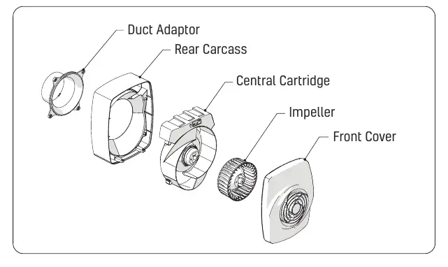
Safety Precautions
- Isolate the mains supply before beginning any installation or maintenance.
- The unit must not be wall-mounted upside down (electronic boards at the bottom) as this voids the warranty.
- Ensure the unit does not affect open-flue appliances (e.g., boilers). Refer to local regulations (e.g., Approved Document J in the UK).
- In kitchens, if installed above a cooker, maintain a minimum distance of 1 metre above the hob.
- Do not use a Type AC RCD with this product.
- The unit will not operate without the front cover in place.
Installation
- Isolate the mains supply.
- Loosen the two screws on the bottom and remove the front cover.
- Pull the central cartridge out from the rear carcass.
- Disconnect the green power connector.
- Connect the power cable and local isolator to the mains as per the wiring diagrams. Tighten the cable gland.
- Insert the rear carcass into the wall duct and fix it to the wall using the provided screws and wall plugs.
- If using a backdraught shutter, insert it fully (do not use if ceiling mounted).
- Insert provided caps into the fixing holes at the top of the rear carcass.
- Reconnect the green power connector and insert the central cartridge into the rear carcass. Fix with four screws.
- Adjust switches 1 and 2 on the central cartridge for desired duty settings.
- Apply the adhesive foam pad over the switches.
- Ensure the impeller is fitted correctly (two clips engaged).
- Replace the front cover and tighten the two screws.
- Reactivate the mains supply.
Wiring
230V Variant: Connect the local isolator to the mains as part of the fixed wiring. Connect the N and L connectors of the fan power cable to the local isolator.
SELV Variant: Connect the red 12V cable from the unit to the red cable on the SELV power supply using the supplied terminal block. Connect the black 12V cable from the unit to the black cable on the SELV power supply.
Settings
Adjust switches 1 and 2 on the central cartridge:
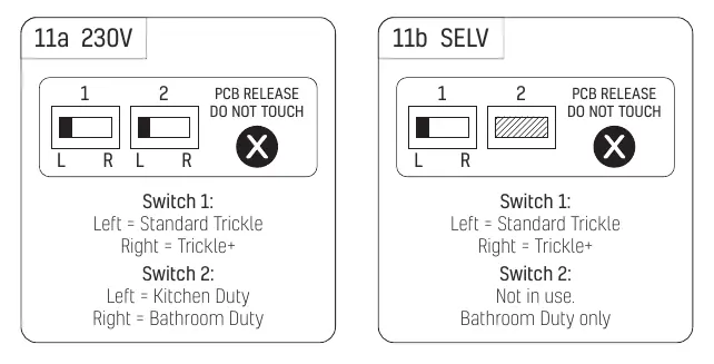
- Switch 1: Left = Standard Trickle, Right = Trickle+
- Switch 2 (230V): Left = Kitchen Duty, Right = Bathroom Duty
- Switch 2 (SELV): Not in use (Bathroom Duty only)
Cleaning and Maintenance
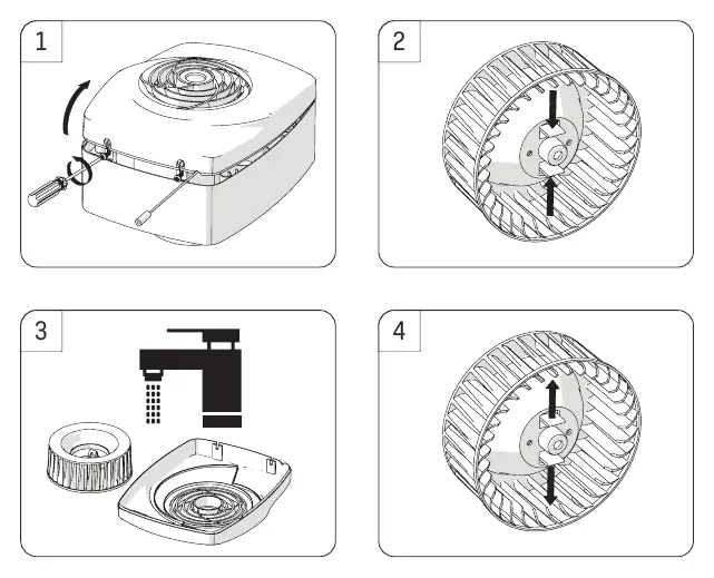
Isolate the unit from the mains supply before cleaning. Remove the front cover, push the impeller clips towards the center, and pull the impeller out. Clean the front cover and impeller in warm soapy water and allow to dry. Do not use solvents or a dishwasher. Clip the impeller back into position and replace the front cover.
Technical Specifications
The unit is designed to operate continuously for up to 5 years without major service. Airflow performance varies by setting (Bathroom/Kitchen Trickle, Trickle+, and Boost). Weights: 230V (1.45kg unboxed, 1.65kg boxed); SELV (1.25kg unboxed, 1.85kg boxed).
Practical help
Common problems
Unit will not operate
Ensure the front cover is correctly fitted and the two screws are tightened. The unit has a safety switch that prevents operation without the cover.
Impeller not spinning
Check that the impeller is correctly seated and the two clips are fully engaged.
Wiring/Power issues
Ensure the local isolator is correctly wired and the green power connector is securely attached to the unit.
Before use
- Isolate the mains supply before starting installation.
- Check that there is sufficient space for the unit in the chosen location.
- Ensure the duct size is 100mm or 125mm (150mm requires an optional adaptor).
- Verify the mounting orientation (do not mount upside down).
- Ensure the front cover is fitted before reactivating power.
Show more Show less
Model compatibility
- Standard duct size: 100mm or 125mm.
- 150mm duct requires optional adaptor (1RDSPIG150).
- Not suitable for use with a Type AC RCD.

Manual page author
Michael Turner
Technical manual editor