HVAC / Ventilation Systems
User Manual for EnviroVent Eco dMEV+ 17V Extract Fan
Quick guide for the EnviroVent Eco dMEV+ 17V extract fan. Includes installation, wiring diagrams, dip switch settings for airflow and humidity, and maintenance instructions.
Quick answers from the manual
Quick answer
- The Eco dMEV+ 17V is a continuous extract fan. Installation requires a 105mm hole. Settings for airflow, timer, and humidity are configured via dip switches on the PCB. p. 10, 11, 12
Key actions
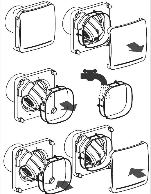
- Clean the filter every two months. p. 13
- Configure settings using dip switches. p. 11, 12
Problems and fixes
Fan never runs on boost
Check humidity sensor setting or room humidity level.
p. 13Maintenance and reset
- Clean filter every two months. p. 13
Technical specifications
| Parameter | Value | Meaning | Pages |
|---|---|---|---|
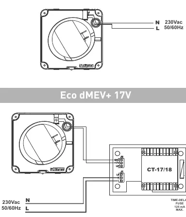
| Voltage | 230Vac 50/60Hz | Power supply requirements. | p. 6, 11 |
| Fuse | 125mA max | Time-delay fuse requirement. | p. 6 |
Where to find it in the PDF
- Installation p. 10, 11
- Wiring Diagrams p. 6, 7, 8, 9
Table of contents
Manual images
Click an image to enlargeQuick guide from the manual
The EnviroVent Eco dMEV+ 17V is a decentralised mechanical extract ventilation fan designed for continuous operation. It is suitable for wall or ceiling mounting. Before installation, ensure the mains supply is disconnected. The unit requires a 105mm hole in the wall or ceiling. If using ducting, use a standard 100mm duct.
Installation
The unit can be mounted on the wall or ceiling using the provided screws and raw plugs. Ensure there are no obstructions to the airflow and that the impeller turns freely. The unit is Class II (double insulated) and does not require an earth connection.
- Make a 105mm hole in the wall or ceiling.
- If installing with ducting, use a 100mm standard duct.
- Introduce the mains cable through the cable entry (5).
- Fix the unit to the wall or ceiling.
- Connect the electrical wiring according to the applicable diagram.
- Mount the protection cover and front grille.
Electrical Connection
The electrical installation must include a double pole switch with a contact clearance of at least 3mm. The unit is designed for a single-phase supply with voltage and frequency as indicated on the rating plate.
Operation and Settings
The fan operates continuously at low speed and constant volume. Settings are adjusted via dip switches located on the electronic circuit board (Fig. 1b). The fan may also operate at high speed (boost) activated by an external switch, light switch, or humidity sensor (depending on the model).
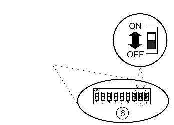
Dip Switch Settings
- Airflow: Configured using SW2, SW3, and SW4.
- Timer: Configured using SW6 and SW7 (1, 5, 15, or 30 minutes).
- Humidity Sensor: Configured using SW8 and SW9 (60%, 70%, 80%, or 90% RH).
Factory Settings: Airflow 8l/s, Timer 1 minute, Humidity 60% RH.
Maintenance
Performance depends on cleaning frequency. We recommend cleaning the filter at least every two months. The fan must always be operated with the filter fitted; using it without the filter invalidates the warranty. Clean the external surface with a cloth lightly impregnated with a soft detergent.
Troubleshooting
If the fan never runs on boost, check if the humidity sensor is set to maximum or if the room humidity is below 60% RH. If the fan always runs on boost, check if the humidity sensor is set to minimum or if the room humidity is above 90% RH.
Practical help
Common problems
Fan never runs on boost
Check if the humidity sensor is set to maximum or if the room humidity is below 60% RH.
Fan always runs on boost
Check if the humidity sensor is set to minimum or if the room humidity is above 90% RH.
Before use
- Ensure mains supply is disconnected before installation.
- Verify the model and voltage/frequency on the rating label.
- Ensure the impeller turns freely.
- Use a double pole switch with at least 3mm contact clearance.
- Ensure the filter is fitted before operation.
Specs in practice
- Constant Volume
- Fan operates continuously at low speed.
- Humidity Sensor
- Adjustable threshold from 60% to 90% RH.
Images and diagrams
- Fig 1a: Filter cleaning procedure.
- Fig 1b: Dip switch locations and identification.
- Fig 3-6: Wiring diagrams for different connection scenarios.
Model compatibility
- Suitable for wall or ceiling mounting.
- Requires 105mm hole.
- If using ducting, use 100mm standard duct.

Manual page author
Emily Carter
User documentation editor
Prepares concise manual descriptions and highlights the most useful setup, operation, and maintenance information for readers.