HVAC / Ventilation Systems
Installation Guide for EnviroVent Filterless Infinity Fan
Comprehensive installation and operation guide for the EnviroVent Filterless Infinity Fan. Includes wiring diagrams, setup instructions, maintenance, and performance specifications for 230V and SELV models.
Quick answers from the manual
Quick answer
- The EnviroVent Filterless Infinity Fan is a ventilation unit for kitchens and bathrooms. Installation requires a competent person, adherence to IET Wiring Regulations, and specific attention to the front cover, which must be fitted for the unit to operate. p. 1, 2, 3, 8
Key actions
- Install the unit p. 8, 9, 10, 11
- Clean the unit p. 15
- Adjust settings p. 10, 13
First start
- Ensure the front cover is fitted, as the unit will not operate without it. p. 11
Show 4 more answers Show less
Problems and fixes
Unit does not operate
Check power supply, internal connectors, and ensure the front cover is fitted.
p. 14Maintenance and reset
- Datalogger data can be reset (except total run time). p. 6, 12
Technical specifications
| Parameter | Value | Meaning | Pages |
|---|---|---|---|
| Power (W) | 3W - 30W | Power consumption varies by setting (Trickle/Boost). | p. 16 |
| Duty (L/s) | 14 L/s - 55 L/s | Airflow performance varies by setting. | p. 16 |
| Weight (Unboxed) | 1.45kg (230V) / 1.25kg (SELV) | Weight of the unit without packaging. | p. 20 |
Where to find it in the PDF
- Installation p. 8, 9, 10, 11
- Wiring Diagrams p. 5
- Cleaning p. 15
Table of contents
Manual images
Click an image to enlargeQuick Guide from the Manual
The EnviroVent Filterless Infinity Fan is designed to improve indoor air quality and reduce humidity in kitchens and bathrooms. This guide covers both 230V and SELV models. Installation must be performed by a competent person. The unit requires a continuous power supply and must not be wired through a light switch. The unit will not operate if the front cover is not correctly fitted.
Installation
Before beginning, isolate the mains supply. Ensure there is adequate space for the unit. Standard installation uses 100mm or 125mm diameter ducting; a 150mm adaptor is available as an optional kit.
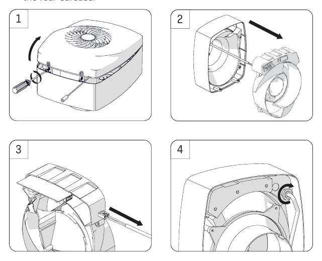
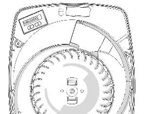
- Loosen the two screws on the bottom of the unit and remove the front cover.
- Pull the central cartridge out from the rear carcass.
- Disconnect the green connector end of the power cable.
- Connect the power cable and local isolator to the mains as per the wiring diagrams. Tighten the cable gland on the rear carcass.
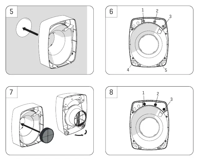
- Insert the rear carcass into the wall duct and fix it to the wall using the four provided screws and wall plugs.
- If using a backdraught shutter, insert it fully (do not use if ceiling mounted).
- Insert the provided caps into the fixing holes at the top of the rear carcass to maintain IP rating and warranty.
- Reconnect the green power connector and insert the central cartridge into the rear carcass. Secure with the four supplied screws.
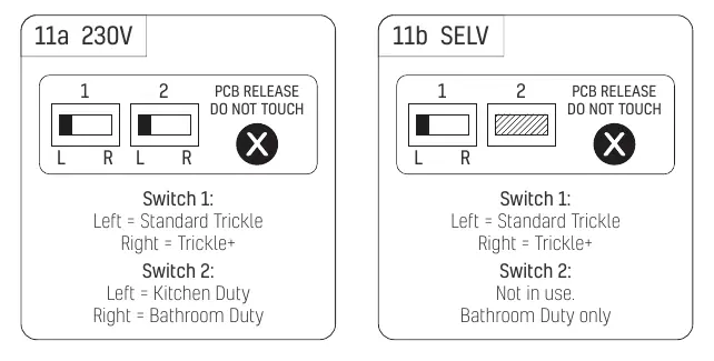
- Adjust switches 1 and 2 on the central cartridge to set the duty (Kitchen/Bathroom and Trickle/Trickle+).
- Apply the adhesive foam pad over the switches.
- Ensure the impeller is fitted correctly with both clips engaged.
- Replace the front cover, ensuring the pullcord sits in the slot, and tighten the screws.
Electrical Connection
Wiring must comply with IET Wiring Regulations (BS7671 in the UK) or equivalent. A suitable local isolator must be incorporated into the fixed wiring. The power cable must be the supplied flexible cable; using solid core cable will void the warranty. The product is not suitable for use with a Type AC RCD.
Operation
The fan features a datalogger and variable speed control. The datalogger tracks total running time, time spent in speeds, humidity periods, and energy usage. Variable speed control allows for 25 increments from the factory set point up to 100% airflow, accessible via the keypad under the front cover.
Cleaning and Maintenance
Isolate the unit from the mains before cleaning. Remove the front cover, push the impeller clips towards the center, and pull the impeller out. Clean the front cover and impeller in warm soapy water and allow to dry. Ensure the small black hole (Intellitrac sensor) is clear of debris. Do not use solvents or a dishwasher. Clip the impeller back into position and replace the front cover.

Technical Specifications
The unit is available in 230V (IPX4) and SELV (IPX5) versions. Performance varies by setting (Bathroom/Kitchen, Trickle/Boost). Boxed unit weight is 1.65kg (230V) or 1.85kg (SELV). Unboxed weight is 1.45kg (230V) or 1.25kg (SELV).
Troubleshooting
If the unit fails to operate, check the power supply, ensure all internal electrical connectors are attached, verify the central cartridge is correctly seated, ensure the impeller spins freely, and confirm the front cover is securely fitted.
Practical help
Common problems
Unit does not operate
Ensure the front cover is fitted, as the unit will not operate without it. Check power supply and internal electrical connectors.
Pullcord not working
Ensure the pullcord is not trapped inside the unit.
Impeller not spinning
Ensure the impeller is fitted correctly and the two clips are fully engaged.
Before use
- Verify the unit is installed by a competent person.
- Check that the duct size (100mm/125mm/150mm) is appropriate for the location.
- Ensure the unit is not wall-mounted upside down.
- Confirm the cowl is positioned at least 300mm away from open-flues.
- If in a kitchen above a cooker, ensure a minimum distance of 1 metre above the hob.
- Ensure the adhesive foam pad is applied over the switches.
Show more Show less
Specs in practice
- 230V vs SELV
- 230V is IPX4 rated; SELV is IPX5 rated and runs on bathroom duty only.
- Variable Speed Control
- Allows adjustment of trickle speeds in 25 increments up to 100% airflow.
Images and diagrams
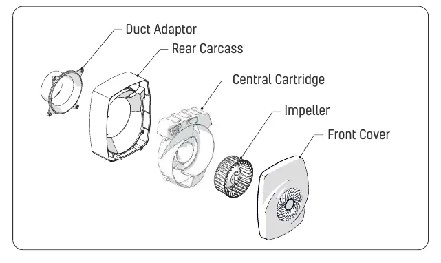
- Exploded view shows the assembly order: Duct Adaptor, Rear Carcass, Central Cartridge, Impeller, Front Cover.
- Wiring diagrams illustrate connections for 230V and SELV power supplies.
- Installation steps 1-15 provide a visual sequence for mounting and wiring.
Model compatibility
- Standard ducting: 100mm or 125mm.
- 150mm ducting requires an optional adaptor.
- Not suitable for use with a Type AC RCD.

Manual page author
Emily Carter
User documentation editor