Electronics / AV Accessories
Setup Guide for Extron MPS 112/112CS Media Presentation Switcher
A comprehensive setup guide for the Extron MPS 112 and 112CS Media Presentation Switchers. Includes installation steps, wiring diagrams for audio and RS-232, audio optimization procedures, and configuration for single or separate switcher...
Table of contents
Manual images
Click an image to enlargeQuick Setup Guide
This guide provides essential instructions for installing and configuring the Extron MPS 112 and 112CS media switchers. Before beginning, ensure all power sources are disconnected. The installation process involves mounting the unit, connecting video and audio inputs/outputs, configuring microphone settings, and establishing RS-232 control if required.
Installation
- Disconnect power: Turn off or disconnect all equipment power sources before starting.
- Mount the unit: Select a mounting option, install the appropriate brackets, and secure the switcher.
- Connect video inputs: Attach up to four VGA, four S-video, and four Video (composite) input devices.
- Connect video outputs: Connect the VGA, S-video, and Video (composite) outputs to the appropriate projector inputs.
- Connect audio inputs: Connect up to 12 audio sources to the audio inputs of the VGA, S-video, or Video (composite) groups. Use 3.5mm stereo mini connectors for VGA group audio and RCA connectors for Video/S-Video groups.
- Connect Mic input: Connect the microphone to the 1/4" connector (MPS 112) or the 3-pole 3.5mm captive screw connector (MPS 112CS).
- Connect audio outputs: Connect audio output devices to the three output groups. Use RCA connectors for Program Audio on the MPS 112 or 3.5mm captive screw connectors on the MPS 112CS.
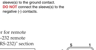
- Connect RS-232 port: If remote control is needed, connect the host RS-232 cable to the 9-pin female connector.
- Connect Power: Power up input/output devices, then connect power to the rear AC connector of the MPS 112.
Optimizing the Audio
To ensure optimal sound quality, follow these steps:
- Reset volume: Press and hold the Mode button, then press and release the Prog Vol Reset button.
- Adjust volume: Select an input with a signal and adjust the audio amplifier volume connected to the Program Audio output.
- Microphone power: Toggle phantom power (15V for MPS 112 or 48V for MPS 112CS) by holding the Mode button for over 2 seconds, then pressing the Mic Power On/Off button.
- Microphone volume: Turn on the microphone using the Mix button. Reset volume by holding Mode and pressing Mic Vol Reset. Adjust using the Mic Volume knob.
Setting the Microphone Talk-over Threshold
The talk-over feature automatically lowers the main program audio when speaking into the microphone.
- Turn on the microphone using the Mix button.
- Speak in a normal voice. If the program audio does not drop moderately, hold the Mix button and turn the Mic Volume knob counter-clockwise to lower the threshold.
- To increase the threshold, hold the Mix button and turn the Mic Volume knob clockwise.
Switcher Operation Modes
The MPS 112 can be configured in two modes by holding the Mode button for more than 2 seconds, then pressing the Single or Separate button.
- Single Switcher Operation: Emulates one switcher with 12 inputs. Selecting an input routes audio/video to the output for that group and the program audio output. All other outputs are muted.
- Separate Switcher Operation: Acts as three independent switchers (VGA/Audio, S-video/Audio, Video/Audio). Each group has its own video and audio output that remains active.
Manufacturer information
Extron Electronics
Practical help
Common problems
Audio volume is not at the desired level
Reset the program audio volume by holding the Mode button and pressing the Prog Vol Reset button, then adjust the amplifier volume.
Microphone is not working
Ensure the correct phantom power (15V for MPS 112 or 48V for MPS 112CS) is enabled and the Mix button is turned on.
Talk-over threshold is too sensitive or not sensitive enough
Adjust the threshold by holding the Mix button and turning the Mic Volume knob counter-clockwise (to lower threshold) or clockwise (to increase threshold).
Before use
- Disconnect all equipment power sources before installation.
- Verify the microphone type and required phantom power (15V vs 48V).
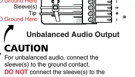
- Ensure audio wiring (balanced vs. unbalanced) matches the connector requirements.
- Do not tin wires when using captive screw connectors.
- Select appropriate mounting brackets for the installation environment.
Specs in practice
- RS-232 Protocol
- 9600 baud, no parity, 8 data bits, 1 stop bit, no flow control.
Images and diagrams
- Mic Input Wiring: Shows correct wiring for balanced and unbalanced microphone inputs on 3-pole 3.5mm connectors.
- Audio Output Wiring: Illustrates balanced vs. unbalanced connections; for unbalanced, connect sleeve to ground but do not connect to negative contacts.
- RS-232 Pinout: Identifies Pin 2 (Tx), Pin 3 (Rx), and Pin 5 (Ground) on the 9-pin female connector.
Model compatibility
- MPS 112CS supports 48V phantom power for microphones, whereas the MPS 112 supports 15V.
- Single mode emulates one switcher with 12 inputs; Separate mode emulates three independent switchers.

Manual page author
David Miller
Documentation analyst
Organizes user manual content into clear summaries, with attention to model details, product context, and everyday usability.