Furniture / Home Furnishing
Falcon Auxiliary Fire Latch for LBR Devices Installation Instructions
Quick installation guide for the Falcon Auxiliary Fire Latch for LBR devices. Includes drilling specifications, mounting instructions, and critical safety warnings for fire door alignment.
Table of contents
Quick guide from the manual
This document provides the installation procedure for the Falcon Auxiliary Fire Latch designed for LBR devices. The latch is a critical safety component that ensures door alignment during a fire by allowing a bolt to extend into the opposite door leaf when the heat-sensitive caps melt.
Installation procedure
- Prepare the edge of the door where the auxiliary fire latch will be installed and the edge of the opposite door for the strike hole according to the dimensions in Figure A. The latch can be installed on either door.
- Secure the auxiliary fire latch using four #6 x 3/4 inch Type AB flat head sheet metal screws as shown in Figure B.
- Install the strike hole plug into the prepared hole on the opposite door leaf.
Safety and limitations
Important: Do not cover the door gap at the auxiliary fire latch with a door edge guard or any similar device, as this will prevent the mechanism from functioning correctly during a fire.
Drilling specifications
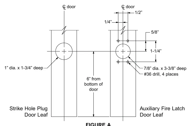
- Auxiliary Fire Latch Door Leaf: Drill four holes using a #36 drill bit. The main hole should be 7/8 inch in diameter and 3-3/8 inches deep.
- Strike Hole Plug Door Leaf: Drill a hole 1 inch in diameter and 1-3/4 inches deep.
- Positioning: The center of the latch assembly should be located 6 inches from the bottom of the door.
Manufacturer information
Falcon Electronics
Practical help
Common problems
Latch fails to engage during a fire
Ensure no door edge guards or similar devices are covering the door gap at the latch location.
Before use
- Verify the door gap is clear of obstructions or edge guards.
- Ensure you have four #6 x 3/4 inch Type AB flat head sheet metal screws.
- Confirm the #36 drill bit is available for the latch mounting holes.
- Measure 6 inches from the bottom of the door for correct vertical placement.
Specs in practice
- Auxiliary Fire Latch hole
- 7/8 inch diameter by 3-3/8 inches deep.
- Mounting screws
- #6 x 3/4 inch Type AB flat head sheet metal screws.
Images and diagrams
- Figure A details the precise drilling locations and depths for both the latch and the strike hole.
- Figure B illustrates the physical mounting of the latch using the specified screws and the placement of the strike hole plug.
Model compatibility
- Designed specifically for LBR devices.
- Can be installed on either the primary or secondary door leaf.

Manual page author
Emily Carter
User documentation editor
Prepares concise manual descriptions and highlights the most useful setup, operation, and maintenance information for readers.