Software / Apps Services
Installation Instructions for Falcon MA-Lock
A comprehensive installation and configuration guide for the Falcon MA-Lock, including step-by-step mounting procedures, mortise rehanding, holdback function setup, and electrical wiring specifications.
Table of contents
Manual images
Jump to the sectionQuick guide from the manual
This document provides installation instructions for the Falcon MA-Lock. Key procedures include mounting the lockcase, installing spindles and lever assemblies, and performing mortise rehanding if required. For electrically locking models (MA851/MA881), specific wiring and electrical requirements must be followed to ensure proper operation and safety.
Installation steps
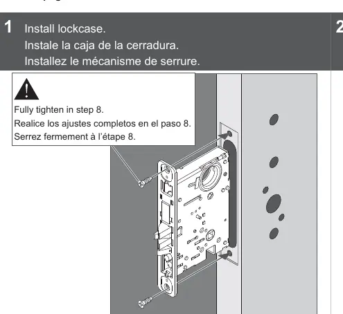
- Install lockcase: Insert the lockcase into the door. Ensure all screws are fully tightened in the final step.
- Install spindles: Insert spindles and screw together, ensuring the spindle with the screw is on the inside.
- Install lever posts: Attach mounting posts to the outside lever.
- Install lever assemblies: Secure the lever assemblies to the door.
- Identify and install trim: Install the appropriate rose, escutcheon, or thumbturn trim as required.
- Secure trim: Fix the trim securely to the door.
- Install cylinder: If included, install the cylinder and ensure all retaining screws are fully tightened.
- Install Armor Front: Attach the armor front plate to the lockcase.
Mortise Rehanding
If the door handing needs to be changed:
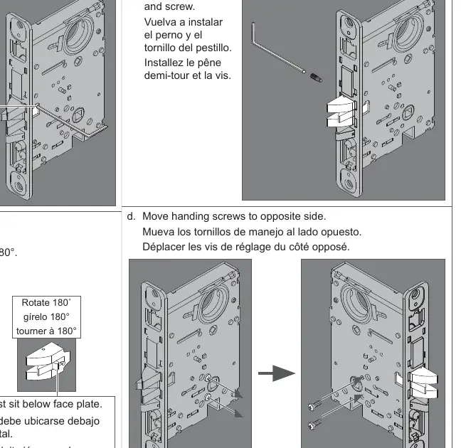
- Remove the screw from the latch bolt.
- Remove the latch bolt and rotate it 180 degrees. Ensure the piece sits below the face plate.
- Reinstall the latch bolt and screw.
- Move the handing screws to the opposite side of the lockcase.
MA551 Holdback Function
To activate: From the unlocked position, rotate the outside lever to retract the latch bolt, then rotate the key 360 degrees counterclockwise and release the lever.
To deactivate: Insert the key and rotate 360 degrees clockwise.
Electrical Requirements
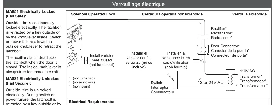
For models MA851 and MA881, ensure installation complies with local electrical codes and NFPA #70. Use a dedicated 12V or 24V transformer. Do not connect locks in series. Transient voltage suppression (varistor rated at 35V) is recommended to protect the lock from electromagnetic interference.
- Voltage: 12V DC +/- 10%
- Operating Current: 0.42 A
- Holding Current: 0.135 A
- Operating Temperature: -31°F to +151°F (-0.5°C to +66°C)
Manufacturer information
Falcon Electronics
Practical help
Common problems
Lock damage due to electrical surges
Install a varistor rated at 35V at the equipment producing transient voltage before connecting the lock to the circuit.
Door does not latch or operate correctly
Always verify that the door operates properly before locking the mortise in place.
Wires damaged during installation
Ensure cables are routed and tucked carefully to avoid pinching or exposure during positioning.
Before use
- Verify door handing and rehand the mortise if necessary.
- Ensure all mounting posts are installed on the outside lever.
- Confirm the spindle with the screw is positioned on the inside.
- Check that the latch bolt sits below the face plate after rotation.
- Ensure all cylinder and mortise retaining screws are fully tightened.
- Confirm electrical transformer voltage matches lock requirements (12V or 24V).
Specs in practice
- MA851 (Fail Safe)
- Outside trim is locked electrically; power failure allows the outside lever to retract the latch.
- MA881 (Fail Secure)
- Outside trim is unlocked electrically; power failure keeps the outside trim locked.
Images and diagrams
- Page 1: Exploded view of lockcase and spindle installation.
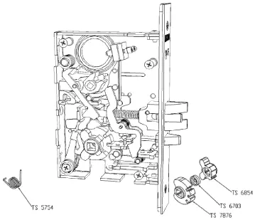
- Page 4: Internal components of the MA551 holdback mechanism.
- Page 6: Wiring diagram for solenoid-operated locks including varistor and transformer connections.
- Page 7: Wiring color codes for RX (Request to Exit) switches.
Model compatibility
- MA12, MA18, and MA161 functions require specific installation steps found on page 5.
- Longitude and Latitude trim have specific alternative installation procedures.

Manual page author
Emily Carter
User documentation editor
Prepares concise manual descriptions and highlights the most useful setup, operation, and maintenance information for readers.