Industrial / Electrical
User Manual for Finder 11 Series 11.31 Light-Sensitive Relay
Quick guide for the Finder 11 Series 11.31 light-sensitive relay. Includes technical specifications, wiring diagrams, LED status indicators, and installation details.
Table of contents
Manual images
Click an image to enlargeQuick guide from the manual
The Finder 11.31 is a light-sensitive relay designed for automatic lighting control based on ambient light levels. It features a 16A contact rating, 17.5mm width, and is designed for 35mm DIN rail mounting. This device is suitable for applications such as external lighting control, cockpit control panels, and internal lighting management.
Product Description
The 11.31 series relay includes a separate light sensor. Key features include:
- Adjustable sensitivity range: 1 to 100 lux.
- Low power consumption.
- LED status indication.
- SELV isolation between contacts and power circuit.
- Double insulation between power supply and light sensor.
- Time delay: 1s ON, 6s OFF to prevent flickering.
- Cadmium-free contacts and sensor.
Technical Specifications
Contact Specifications
- Configuration: 1 NO (SPST-NO)
- Rated current/Maximum peak current: 16/30 A
- Rated voltage/Maximum switching voltage: 250/400 V AC
- Rated load AC1: 4000 VA
- Rated load AC15 (230 V AC): 750 VA
- Minimum switching load: 1000 mW (10/10 mA)
Power Supply Specifications
- Nominal voltage (UN): 12...24 V AC (50/60 Hz) / DC
- Operating range: 10.2...28.8 V AC / 10.2...32 V DC
- Rated power: 2.5 VA / 0.9 W
Environmental & Protection
- Ambient temperature range: -25 to +55°C
- Protection rating: IP20 (relay) / IP54 (sensor)
Installation and Wiring
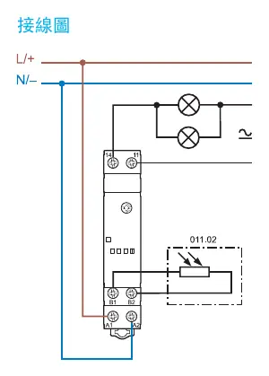
The device is designed for 35mm rail (EN 60715) mounting. Ensure the wiring follows the provided diagram, connecting the L/+ and N/- power lines to the relay and the light sensor to terminals B1 and B2.
Wiring Requirements
- Maximum wire size (solid): 1 x 6 / 2 x 4 mm²
- Maximum wire size (stranded): 1 x 4 / 2 x 2.5 mm²
- Stripping length: 9 mm
- Maximum cable length from relay to sensor: 50 m (2 x 1.5 mm²)
LED Status
The LED provides visual feedback on the relay state:
- LED OFF: Power OFF, Output Contact OPEN.
- LED ON (Blinking): Power ON, Output Contact OPEN.
- LED ON (Solid): Power ON, Output Contact CLOSED.
Accessories
The following accessories are compatible with the 11.31 series:
- 011.02: Standard light sensor (included).
- 011.03: Flush-mount light sensor.
- 060.48: Label tags (48 labels, 6 x 12 mm).
Note: Sensors 011.02 and 011.03 are not compatible with model 11.71.0.024.1001.
Manufacturer information
Finder S.p.A.
Practical help
Common problems
Relay not switching correctly.
Check the sensitivity threshold setting (1-100 lux) and ensure the light sensor is not obstructed or receiving direct artificial light interference.
Wiring issues or connection errors.
Verify the supply voltage is within 12-24V AC/DC and ensure the sensor cable length does not exceed 50m.
Before use
- Verify supply voltage is 12-24V AC/DC.
- Ensure a 35mm DIN rail (EN 60715) is available for mounting.
- Check that the light sensor (011.02 or 011.03) is correctly connected to terminals B1 and B2.
- Confirm load requirements do not exceed 16A.
- Ensure the environment temperature is between -25°C and +55°C.
Images and diagrams
- Wiring Diagram: Shows connection of L/+ and N/- to the relay, with the light sensor connected to terminals B1 and B2.
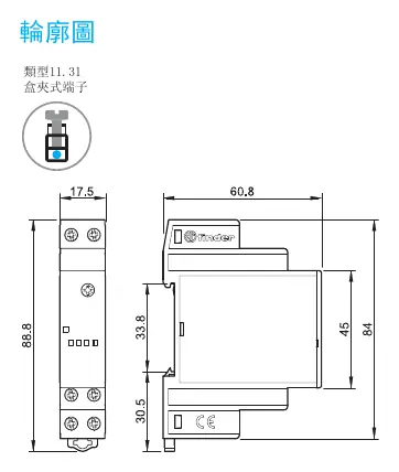
- Outline Drawing: Shows dimensions (17.5mm width) for DIN rail mounting.
Model compatibility
- Compatible with 011.02 (standard) and 011.03 (flush-mount) light sensors.
- Not compatible with model 11.71.0.024.1001.

Manual page author
Emily Carter
User documentation editor
Prepares concise manual descriptions and highlights the most useful setup, operation, and maintenance information for readers.