Industrial / Commercial Timers
Finder 12.A4 Digital Astro Time Switch
Quick guide for the Finder 12.A4 Digital Astro Time Switch. Learn how to program Astro SUNSET/SUNRISE functions, configure 0-10V/PWM outputs, and manage manual overrides.
Table of contents
Manual images
Click an image to enlargeQuick guide from the manual
The Finder 12.A4 is a digital astro time switch designed to control outputs based on geographic sunrise and sunset times or specific timed events. It features a 0-10V or PWM signal output that can be programmed to ramp up or down at a specific rate. The device includes a joystick for navigation and manual override.
Device description
The device features a backlit display (active only when externally powered) and a joystick interface. Key indicators include:
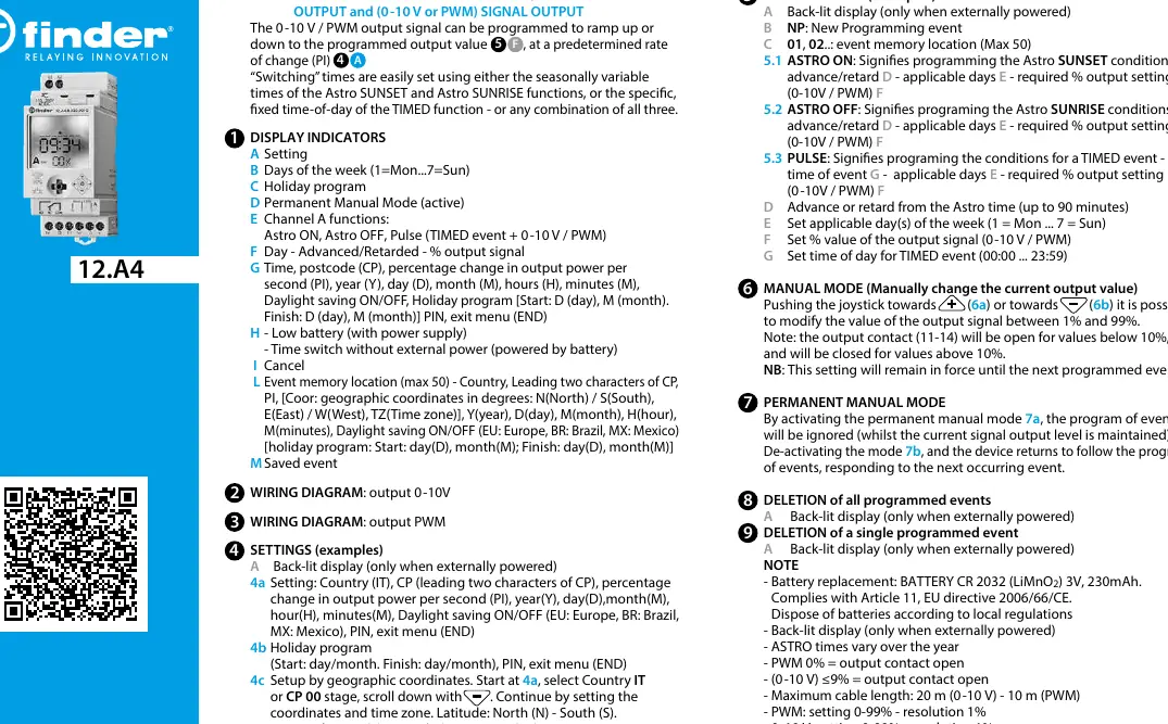
- A: Setting mode
- B: Days of the week (1=Mon to 7=Sun)
- C: Holiday program
- D: Permanent Manual Mode
- E: Channel A functions (Astro ON, Astro OFF, Pulse)
- F: Day/Advanced/Retarded/Output signal percentage
- G: Time, postcode, PI (ramp rate), year, day, month, daylight saving, PIN
- H: Low battery indicator
Installation and wiring
The device is designed for panel mounting. Ensure the circuit connected to PWM/0-10 terminals has at least basic insulation relative to the line circuit. Terminals require a nominal torque of 0.8 Nm. Wiring diagrams are provided for both 0-10V and PWM output configurations. Maximum cable length is 20m for 0-10V and 10m for PWM.
Programming
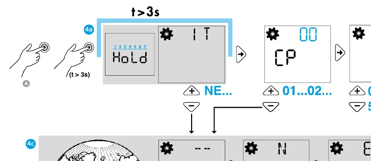
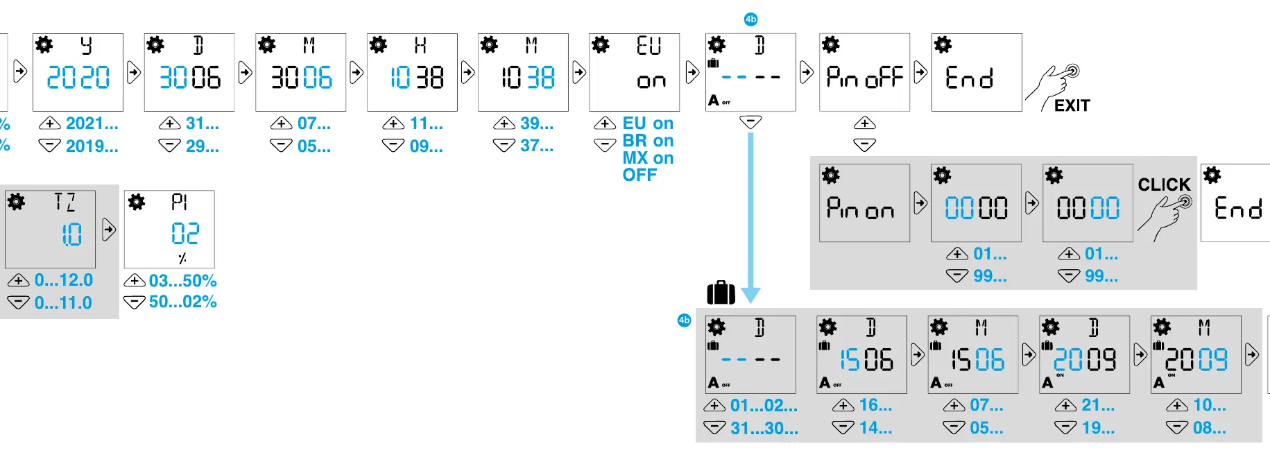
Programming is performed using the joystick. Key programming modes include:
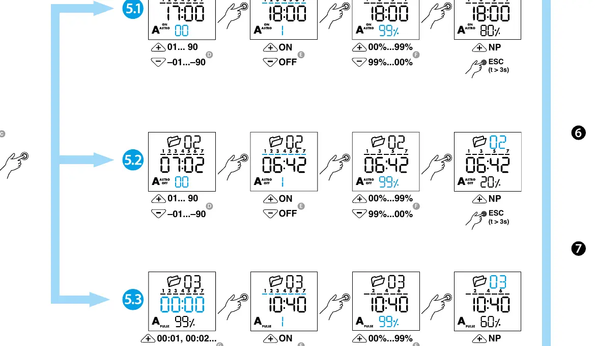
- Astro ON/OFF: Sets conditions based on Astro SUNSET/SUNRISE times, including advance/retard settings and output percentage.
- Pulse (TIMED event): Sets conditions for a specific time of day (00:00 to 23:59).
- Geographic Setup: Configure by selecting Country or Postcode, then setting coordinates (Latitude/Longitude) and Time Zone.
- Holiday Program: Allows setting start and finish dates for holiday periods.
Manual operation
The device supports two manual modes:
- Manual Mode: Use the joystick to modify the output signal between 1% and 99%. This setting remains in force until the next programmed event. Note that the output contact (11-14) is open for values below 10% and closed for values above 10%.
- Permanent Manual Mode: Activates a mode where the program of events is ignored while maintaining the current signal output level.
Maintenance and technical data
The device uses a CR 2032 (LiMnO2) 3V, 230mAh battery. Battery replacement must be performed only by the manufacturer or competent personnel. The device operates within a temperature range of -20 to +50°C and has an IP20 protection rating.
Manufacturer information
Finder S.p.A.
Practical help
Common problems
Output contact remains open
Check if the PWM value is 0% or if the 0-10V signal is <=9%. The contact opens at these levels.
Display is not lit
The back-lit display only functions when the device is externally powered.
Device does not follow the programmed schedule
Check if Permanent Manual Mode is active. If active, the program is ignored.
Before use
- Verify power supply is 110-230V AC/DC.
- Ensure wiring matches the required output type (0-10V or PWM).
- Confirm the CR 2032 battery is installed.
- Check that the installation environment is between -20 and +50°C.
- Ensure the installer is qualified for the installation.
Specs in practice
- Astro SUNSET/SUNRISE
- Automatic switching times that vary throughout the year based on geographic location.
Images and diagrams
- Wiring Diagram: Illustrates connections for L, N, and the specific output (0-10V or PWM).
- Joystick: Used for navigating menus and performing manual overrides.
Model compatibility
- Max cable length: 20m for 0-10V, 10m for PWM.
- Output contact: 1 CO (SPDT) 16A 250V AC.
- Pollution Degree 2, Impulse Voltage 4000V.

Manual page author
David Miller
Documentation analyst
Organizes user manual content into clear summaries, with attention to model details, product context, and everyday usability.