Industrial / Electrical
User Manual for Finder 14.61-P Staircase Timer Relay
Quick guide for the Finder 14.61-P Multifunction Staircase Timer Relay. Learn about wiring diagrams, function settings, installation, and technical specifications.
Table of contents
Manual images
Click an image to enlargeQuick Guide from the Manual
The Finder 14.61-P is a multifunction staircase timer relay designed for 230V AC systems. It features push-in terminals for easy installation and supports both 3-wire and 4-wire configurations. The device offers adjustable timing from 0.5 to 20 minutes and includes specific functions for maintenance lighting and permanent ON modes.
Product Overview
The front panel of the device includes:
- A: Rotary function selector
- B: Time setting dial
- C: LED status indicator
Installation and Wiring
The device features doubled N and 3 terminals, allowing for top or bottom connection. Important: Ensure the N supply to the load is routed directly from the power source and not through the device. Do not use the doubled N terminal for the load supply.
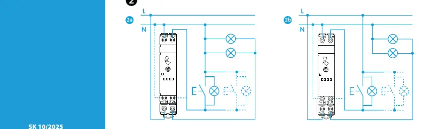
Wiring Configurations:
- 3-Wire Connection (2a): Button connected to N.
- 4-Wire Connection (2b): Button connected to L.
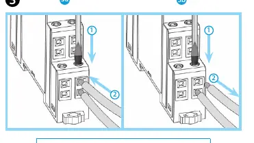
Terminal Connection: Use the push-in terminals for wire cross-sections between 0.75 and 2.5 mm² (18-14 AWG). Strip wires to 10mm.
Functions
The device supports the following operating modes:
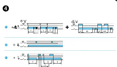
- 4a: Impulse-controlled switch with switch-off warning + maintenance lighting: Pressing the button for ≥5s switches the output contact ON for 60 minutes, then switches OFF. This is suitable for cleaning. The duration can be interrupted by pressing the button again for ≥5s.
- 4b: Permanent ON: Keeps the output contact closed.
- 4c: Staircase Timer: Pressing the button closes the output contact and starts the set timing period. Pressing the button again during the timing period restarts the timer.
Technical Specifications
- Nominal Voltage: 230V AC (50/60 Hz)
- Voltage Range: 184V to 253V AC
- Contact: 1 NO (SPST-NO), 10A 230V AC
- Load Capacity: 1000W (Incandescent), 300W (CFL/LED)
- Time Range: 0.5 to 20 minutes
- Operating Temperature: -10°C to +60°C
Operating Conditions
To prevent interference from transformers, motors, contactors, or power lines, ensure wiring to terminals is as short as possible. If necessary, suppress interference using an RC element, varistor, or surge protector connected between L-N and/or 3-4. The maximum length of wiring to buttons is 200m.
Manufacturer information
Finder S.p.A.
Practical help
Common problems
Interference from motors or contactors
Ensure wiring to terminals is as short as possible. If interference persists, install an RC element, varistor, or surge protector between L-N and/or 3-4.
Load does not switch correctly
Verify that the N supply to the load is routed directly from the power source and not through the device terminals.
Before use
- Verify supply voltage is 230V AC.
- Ensure wire cross-section is between 0.75 and 2.5 mm².
- Strip wires to exactly 10mm.
- Determine if your installation requires a 3-wire (button to N) or 4-wire (button to L) configuration.
- Check that the total load does not exceed 1000W (incandescent) or 300W (CFL/LED).
Images and diagrams
- 2a: 3-wire connection diagram with button connected to Neutral.
- 2b: 4-wire connection diagram with button connected to Line.
- 3a/3b: Instructions for inserting and releasing wires in push-in terminals.
Model compatibility
- Maximum length of wiring to buttons is 200m.
- Compatible with incandescent, CFL, and LED loads.

Manual page author
Emily Carter
User documentation editor
Prepares concise manual descriptions and highlights the most useful setup, operation, and maintenance information for readers.