Tools / Electronic Test Equipment
User Manual for Fluke 2052R/2062R Wire Tracer and 2000T Transmitter
Comprehensive user guide for the Fluke 2052R/2062R Wire Tracer and 2000T Transmitter. Includes setup instructions, transmitter connection diagrams, receiver operating modes, and battery replacement procedures.
Quick answers from the manual
Quick answer
- The Fluke 2052R/2062R Wire Tracer system uses a 2000T transmitter to inject a signal into a circuit, which is then traced by the receiver. Users can select different modes (Smart Sensor, Tip Sensor, Breaker, NCV) on the receiver to locate wires and breakers accurately. p. 1, 2
Key actions
- Connect the 2000T transmitter to the circuit. p. 1
- Select the appropriate mode on the receiver. p. 1
Maintenance and reset
- Replace batteries in the 2052R, 2062R, and 2000T units when power is low. p. 2
Where to find it in the PDF
- Transmitter Connections and Receiver Modes p. 1
- Tracing Procedures and Maintenance p. 2
Table of contents
Manual images
Click an image to enlargeQuick Guide
The Fluke 2052R/2062R Wire Tracer system, paired with the 2000T Transmitter, is designed to locate wires and breakers in electrical systems. The transmitter injects a signal into the circuit, which is then detected by the receiver. Ensure the transmitter is properly connected to the circuit before beginning the trace.
Transmitter (2000T) Setup
The 2000T Transmitter must be connected to the circuit to be traced. It supports various connection types, including GFI and RCD protected circuits. Ensure the transmitter is set to the appropriate signal strength (High or Low) based on the tracing requirements.
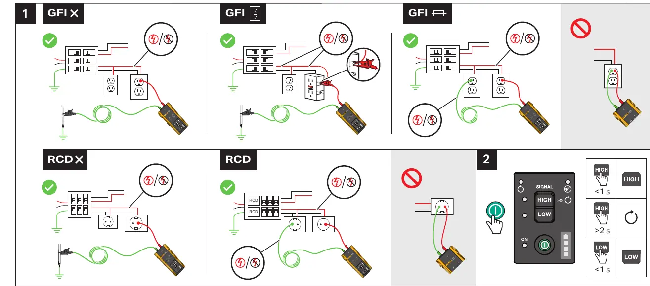
- High Signal: Use for general tracing.
- Low Signal: Use for precise tracing to minimize signal bleed.
- Connection: Connect the transmitter leads to the circuit. Ensure proper polarity and grounding as indicated in the connection diagrams.
Receiver (2052R/2062R) Operation
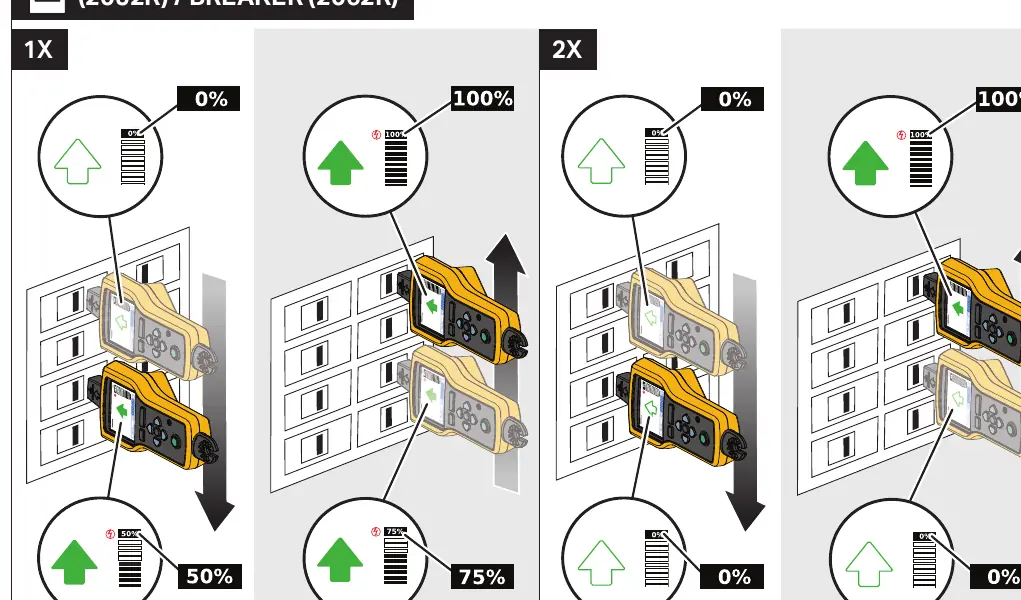
The receiver offers multiple modes to assist in wire and breaker identification. Use the MODE button to cycle through available options:
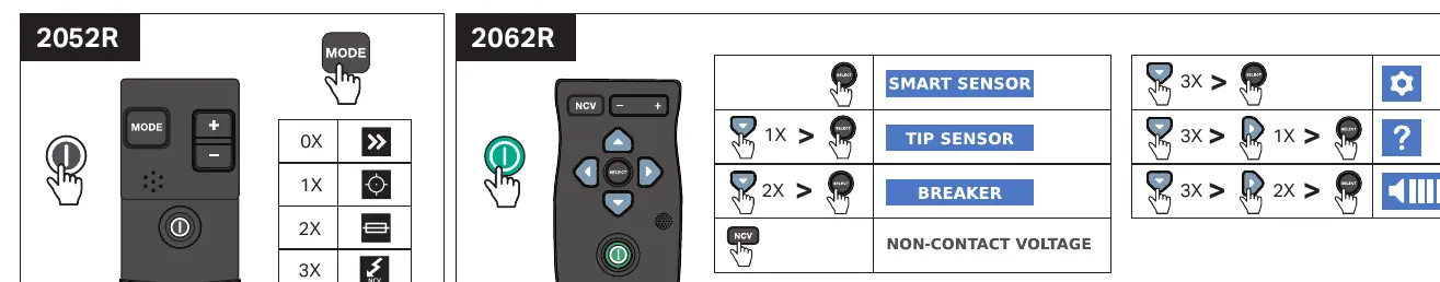
- Smart Sensor: Used for general wire tracing.
- Tip Sensor: Used for precise location of wires.
- Breaker: Used to identify specific circuit breakers.
- NCV (Non-Contact Voltage): Used to detect live voltage without direct contact.
Tracing Procedures
Follow these procedures for effective wire and breaker tracing:
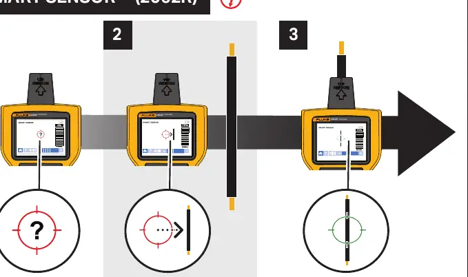
- Smart Sensor (2062R): Follow the on-screen guidance to track the signal path.
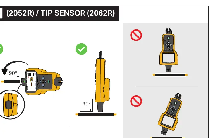
- Tip Sensor: Hold the receiver at a 90-degree angle to the wire for optimal detection.
- Breaker Tracing: Scan the breakers to identify the one associated with the transmitter signal.
Note: Maintain a distance of at least 1 meter between the transmitter and the receiver during operation to prevent signal interference.
Maintenance
Regular maintenance ensures the longevity and accuracy of the device.
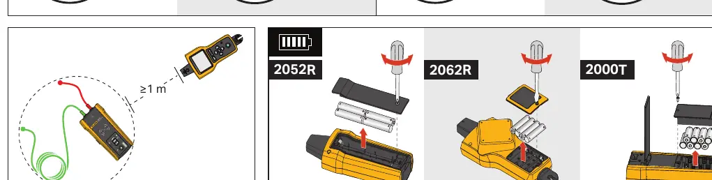
- Battery Replacement: If the battery level is low, replace the batteries in the 2052R/2062R receiver and the 2000T transmitter. Open the battery compartment cover, replace with fresh batteries, and secure the cover.
Manufacturer information
Fluke Corporation
Practical help
Common problems
Signal interference or inaccurate tracing
Ensure the receiver is at least 1 meter away from the transmitter. Adjust the signal strength (High/Low) on the transmitter.
Difficulty identifying the correct breaker
Ensure the transmitter is properly connected to the circuit and the receiver is set to 'Breaker' mode.
Before use
- Check battery levels for both the transmitter and receiver.
- Ensure the transmitter is correctly connected to the target circuit.
- Verify the transmitter signal strength setting (High/Low).
- Ensure the receiver is set to the correct mode (Smart Sensor, Tip Sensor, Breaker, or NCV).
Images and diagrams
- Transmitter connection diagrams show how to connect to GFI and RCD circuits.
- Receiver mode selection diagrams illustrate how to switch between Smart Sensor, Tip Sensor, Breaker, and NCV modes.
- Tracing diagrams demonstrate the correct orientation (90 degrees) for the Tip Sensor.
- Battery replacement diagrams show the location of the battery compartments for all units.
Model compatibility
- The 2052R/2062R receivers are designed to work with the 2000T transmitter.

Manual page author
Emily Carter
User documentation editor
Prepares concise manual descriptions and highlights the most useful setup, operation, and maintenance information for readers.