Tools / Electronic Test Equipment
Quick Reference Guide for Fluke 2052R/2062R Wire Tracer and 2000T Transmitter
A quick reference guide for the Fluke 2052R/2062R Wire Tracer and 2000T Transmitter. Includes setup, connection diagrams for GFI/RCD circuits, sensor mode selection, and battery replacement instructions.
Quick answers from the manual
Quick answer
- The Fluke 2052R/2062R Wire Tracer and 2000T Transmitter are used to trace wires and identify breakers. Connect the transmitter to the circuit, select the appropriate mode on the receiver, and use the sensors to locate the wire or breaker. p. 1, 2
Key actions
- Connect the 2000T Transmitter to the circuit using the appropriate GFI/RCD diagram. p. 1
- Select the desired mode (Smart Sensor, Tip Sensor, Breaker, NCV) on the receiver. p. 1
First start
- Install batteries in the 2052R, 2062R, and 2000T units. p. 2
Maintenance and reset
- Replace batteries when low power is indicated. p. 2
Technical specifications
| Parameter | Value | Meaning | Pages |
|---|---|---|---|
| Signal Strength | High / Low | Adjustable transmitter output | p. 1 |
Where to find it in the PDF
- Transmitter Connections and Receiver Modes p. 1
- Sensor Usage and Battery Replacement p. 2
Table of contents
Manual images
Click an image to enlargeQuick Guide from the Manual
This guide provides essential instructions for operating the Fluke 2052R/2062R Wire Tracer and the 2000T Transmitter. It covers proper connection methods for different circuit types, signal settings, sensor modes, and maintenance procedures like battery replacement.
Transmitter (2000T) Connections
The 2000T Transmitter is used to inject a signal into the circuit. Ensure the transmitter is connected correctly based on the circuit type:
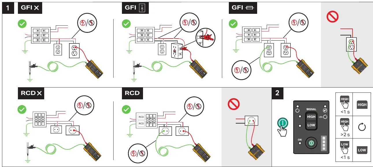
- GFI/RCD Circuits: Follow the specific wiring diagrams provided in the manual to ensure the signal is injected without tripping the GFI or RCD.
- Signal Strength: The transmitter allows for High and Low signal settings. Use the power button to toggle between these modes. Hold for >2s to switch, or <1s to adjust.
- Distance: Maintain a distance of at least 1 meter between the transmitter and the receiver during operation to avoid interference.
Receiver (2052R/2062R) Modes
The receivers offer different modes depending on the task:
- Smart Sensor (2062R): Used for general wire tracing.
- Tip Sensor (2052R/2062R): Used for precise location. Hold the receiver at a 90-degree angle to the surface.
- Breaker Mode (2052R/2062R): Used for identifying breakers.
- NCV (Non-Contact Voltage): Used for detecting live voltage.
Use the Mode button to cycle through these options (0X, 1X, 2X, 3X) as indicated on the device display.
Using Sensors
For optimal performance, ensure the receiver is oriented correctly:
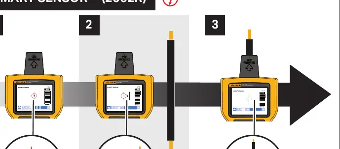
- Smart Sensor: Follow the visual cues on the screen to track the wire path.
- Tip Sensor: Keep the sensor tip perpendicular (90°) to the surface being traced.
- Breaker Identification: Follow the 1X/2X mode indicators to track signal strength from 0% to 100% to identify the correct breaker.
Battery Replacement
If the device indicates low battery, replace the batteries as follows:
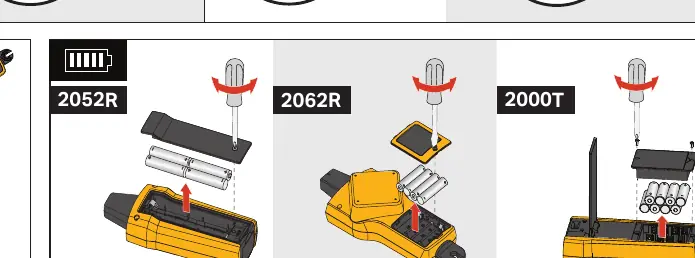
- 2052R: Open the battery compartment on the back of the unit.
- 2062R: Open the battery compartment on the back of the unit.
- 2000T: Open the battery compartment on the back of the transmitter.
Ensure all batteries are installed with the correct polarity.
Manufacturer information
Fluke Corporation
Practical help
Common problems
Signal interference or weak signal
Ensure the transmitter is at least 1 meter away from the receiver and check the signal strength setting (High/Low).
Difficulty identifying the correct breaker
Ensure you are using the correct mode (1X/2X) and that the signal strength is clearly increasing as you approach the correct breaker.
Before use
- Check battery levels for both transmitter and receiver.
- Ensure the transmitter is connected to the circuit according to the GFI/RCD diagrams.
- Select the appropriate mode on the receiver (Smart Sensor, Tip Sensor, Breaker, or NCV).
- Verify the signal strength setting on the transmitter.
Specs in practice
- Signal High/Low
- Adjusts the transmitter output power to suit different circuit conditions.
- 90° Orientation
- The Tip Sensor must be held perpendicular to the surface for accurate tracing.
Images and diagrams
- The manual provides specific wiring diagrams for GFI and RCD circuits to prevent accidental tripping.
- Visual indicators show the correct 90-degree angle for the Tip Sensor.
Model compatibility
- 2062R includes Smart Sensor functionality, while 2052R focuses on Tip Sensor and other modes.
- Ensure the 2000T Transmitter is compatible with the receiver model being used.

Manual page author
Michael Turner
Technical manual editor
Reviews PDF manuals for structure, safety notes, and practical product details so readers can find the right information quickly.