Electronics / Speakers & Soundbars
Focal FDP SPORT V2 Amplifier Configuration Guide
Comprehensive configuration and wiring guide for the Focal FDP SPORT V2 amplifier. Includes setup instructions for 4-channel, 2-channel bridged, and 3-channel modes, plus troubleshooting and technical specifications.
Table of contents
Manual images
Click an image to enlargeQuick Guide from the Manual
The Focal FDP SPORT V2 is a 4-channel Class D amplifier designed for moto and all-terrain applications. This manual provides the necessary steps to configure the amplifier for three primary modes: 4-Channel Stereo, 2-Channel Bridged Stereo, and 3-Channel Stereo/Bridged Mono. Proper configuration requires setting the input switches, crossover modes (HP/LP), and gain levels according to your specific speaker setup.
Control Settings
The amplifier features a control panel for adjusting audio output. Key controls include:
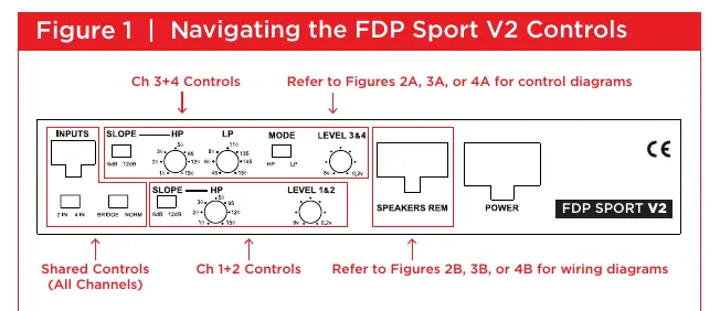
- INPUTS: Select between 2IN or 4IN depending on your source signal.
- SLOPE: Choose between 6dB/octave (gradual) or 12dB/octave (sharper) roll-off.
- MODE: Select the crossover mode (HP, LP, or Full Range).
- HP/LP Controls: Adjust the frequency cut-off points.
- LEVEL: Match the source output level to the amplifier input.
Configuration Modes
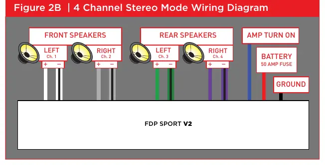
4-Channel Stereo Mode
Used for standard stereo setups. Set the NORMAL/BRIDGED switch to NORM. Configure channels 1+2 and 3+4 independently using the crossover controls. Motorcycles typically use an HP setting of 120Hz.
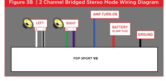
2-Channel Bridged Stereo Mode
Used for higher power output. Set the switch to BRIDGED. Use only the Rear Input Channels 3+4. Set the slope to 12dB.
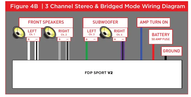
3-Channel Stereo & Bridged Mono Mode
Combines stereo speakers with a subwoofer. Use channels 1+2 for HP stereo and channels 3+4 for LP mono subwoofer. Adjust the LP control for the subwoofer and HP control for the stereo speakers.
Wiring and Connections
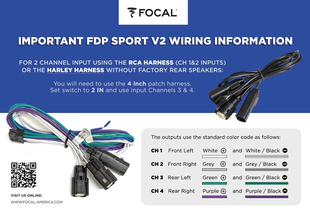
Always respect channel polarity (+ and -) when connecting speakers. Ensure the 50A fuse is installed at the battery. Use the provided Harley Molex harnesses if applicable. Refer to the specific wiring diagrams for your chosen configuration mode to ensure correct speaker and power connections.
Troubleshooting
If you encounter issues, check the following:
- Focal sign does not light: Verify voltage at power and REM terminals (12-15V), check REM wire connection, ground, and all fuses (including the 50A battery fuse and internal fuses).
- Amplifier blows fuse: Check for reversed power and ground polarity.
- Focal sign flashing: The unit may be overheating; ensure adequate ventilation. If cold, it may indicate an internal fault.
- No sound: Check source signal, speaker connections for shorts, and ensure switches are in the correct positions for your setup.
Technical Specifications
- Power Output: 4x150W RMS @ 4 ohm, 4x200W RMS @ 2 ohm, 2x400W RMS Bridged @ 4 ohm.
- Frequency Response: 20Hz - 30KHz.
- Protection: DC, Short Circuit, Thermal, Polarity Reversal.
- Dimensions: 8 1/4" x 5" x 1 5/8" (208mm x 127mm x 41mm).
Manufacturer information
Focal
Practical help
Common problems
Focal sign does not light
Measure voltage at power and REM terminals (must be 12-15V). Check REM wire, ground connection, and all fuses (battery and internal).
Amplifier blows fuse
Check for reversed power and ground polarity at the amplifier and battery.
Focal sign is flashing
If hot, allow to cool and improve ventilation. If cold, it indicates an internal fault; disconnect speaker harness and check for shorts.
No sound
Verify source signal, check for short circuits in speaker wires, and ensure crossover switches are not set to conflicting modes (e.g., BP mode with overlapping frequencies).
Before use
- Ensure power and ground connections are tight and have correct polarity.
- Verify voltage at power and REM terminals is between 12 and 15 volts.
- Select the correct configuration mode (4-channel, 2-channel bridged, or 3-channel) via the switches.
- Set crossover switches (HP/LP) according to your speaker requirements.
- Check that the 50A fuse is installed at the battery.
- Ensure the amplifier has adequate ventilation; do not mount flush in a hole.
Specs in practice
- 4 x 150W RMS @ 4 ohm
- Power output per channel in standard 4-channel stereo mode.
- 2 x 400W RMS Bridged @ 4 ohm
- Power output in bridged mode; do not bridge into 2 ohms.
- HPF 10-150Hz
- High Pass Filter range; use to block low frequencies from speakers.
- LPF 45-150Hz
- Low Pass Filter range; use to block high frequencies from subwoofers.
Images and diagrams
- Figure 1: Overview of amplifier controls including inputs, slope, HP/LP filters, and gain levels.
- Figure 2B/3B/4B: Wiring diagrams for different speaker configurations.
- Wiring Information: Color code guide for speaker outputs (White, Grey, Green, Purple).
Model compatibility
- Do not bridge the amplifier into 2 ohms.
- Motorcycles typically require an HP setting of 120Hz.
- If using 1 set of RCA inputs for 3-channel mode, set the 2IN/4IN switch to 2IN.

Manual page author
Emily Carter
User documentation editor
Prepares concise manual descriptions and highlights the most useful setup, operation, and maintenance information for readers.