Electronics / Amplifiers Receivers
User Manual for SounDigital 100K HV EVO Amplifier
Quick guide for the SounDigital 100K HV EVO amplifier. Includes installation instructions, wiring diagrams for high-voltage battery systems, gain adjustment procedures, and LED status indicator explanations.
Table of contents
Manual images
Click an image to enlargeQuick Guide
The SounDigital 100K HV EVO is a high-voltage Class D amplifier designed for professional audio systems. Warning: This equipment involves high voltage and must be installed only by qualified professionals trained in electrical safety standards. Never touch the amplifier output terminals while the system is energized.
Package Contents
- 1x 100K HV EVO Amplifier
- 1x Owner's Manual
- 1x 2.5mm Allen Key
- 1x 4.0mm Allen Key
- 1x Link Cable
- 1x Promotional Sticker
Installation
Before starting, disconnect the negative (-) terminal of the vehicle battery. Ensure the amplifier is installed in a well-ventilated area, away from water, moisture, or dust. Do not install in the engine compartment.
Electrical Sizing and Safety
- Power Cables: Use 35mm² (2 AWG) cables for HV power input and 2.5mm² (13 AWG) for 12V remote power.
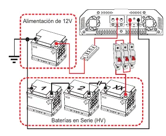
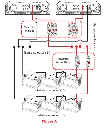
- Battery Connection: Batteries must be connected in series. Use a C-100A circuit breaker for every four batteries in the series.
- Protection: A 3A fuse is required on the 12V remote line.
- Grounding: Use rubber O-rings when passing cables through metal walls to prevent short circuits.
Audio Connections
The amplifier features both RCA (unbalanced) and XLR (balanced) inputs. Important: Never connect or use RCA and XLR inputs simultaneously; use only one input standard at a time. Do not connect or disconnect RCA cables while the amplifier is powered on.
Gain Adjustment
To adjust the gain:
- Disconnect output cables from the amplifier.
- Set gain to minimum.
- Turn on the head unit and remote activation.
- Play a 60Hz sine wave at 70% volume.
- Gradually increase gain until the "CLIP" LED flashes.
- Back off the gain until the "CLIP" LED is completely off.
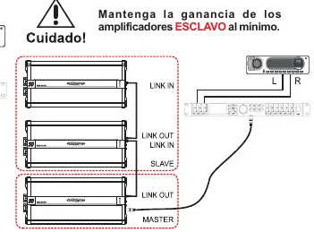
If using the "Link" system, perform this procedure only on the MASTER amplifier with the link cable disconnected, then connect the link cable and set slave amplifiers to minimum gain.
LED Indicators
- Blue LED: Solid indicates power on. Flashing 10 times indicates 12V supply voltage is out of range (<8.9V or >16V).
- Red LED: Flashing 10 times indicates input voltage out of range (400V). Solid indicates thermal protection (80°C limit reached).
- Yellow LED: Indicates audio distortion. If flashing 10 times, it indicates a short circuit or low impedance at the output terminals.
Practical help
Common problems
Audio cuts out and Blue LED flashes 10 times
The 12V supply voltage is too low (16V). Check your 12V power source.
Audio cuts out and Red LED flashes 10 times
The input voltage is out of the operating range (400V). Verify your high-voltage battery bank.
Audio cuts out and Red LED stays on
The amplifier has reached the thermal limit of 80°C. Keep the amplifier on until it cools down and audio restores.
Audio cuts out and Yellow LED flashes 10 times
There is a short circuit or low impedance at the output terminals. Check speaker wiring.
Yellow LED turns on or flashes during playback
The signal is distorted. Reduce the amplifier gain or the head unit volume.
Before use
- Ensure installation is performed by a qualified professional.
- Disconnect the negative (-) battery terminal before starting installation.
- Verify battery voltage is within the 12.6V - 14.4V DC range.
- Ensure the amplifier is installed in a ventilated area.
- Use appropriate cable gauges (35mm² / 2 AWG for HV power).
- Install a C-100A circuit breaker for every four batteries in the series.
Specs in practice
- Tensión de Trabajo
- Operating voltage range (70VDC to 400VDC).
- Consumo Máximo
- Maximum current draw at 226V (470A).
- Eficiencia Total
- Overall efficiency (94%).
- Frecuencia de respuesta
- Frequency response range (-3dB): 5Hz - 10kHz.
Images and diagrams
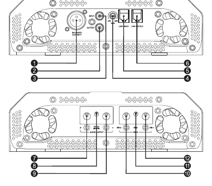
- Panel Layout: Identifies input/output connectors, gain control, and LED indicators.
- Electrical Installation: Shows connection of HV batteries in series with a C-100A circuit breaker.
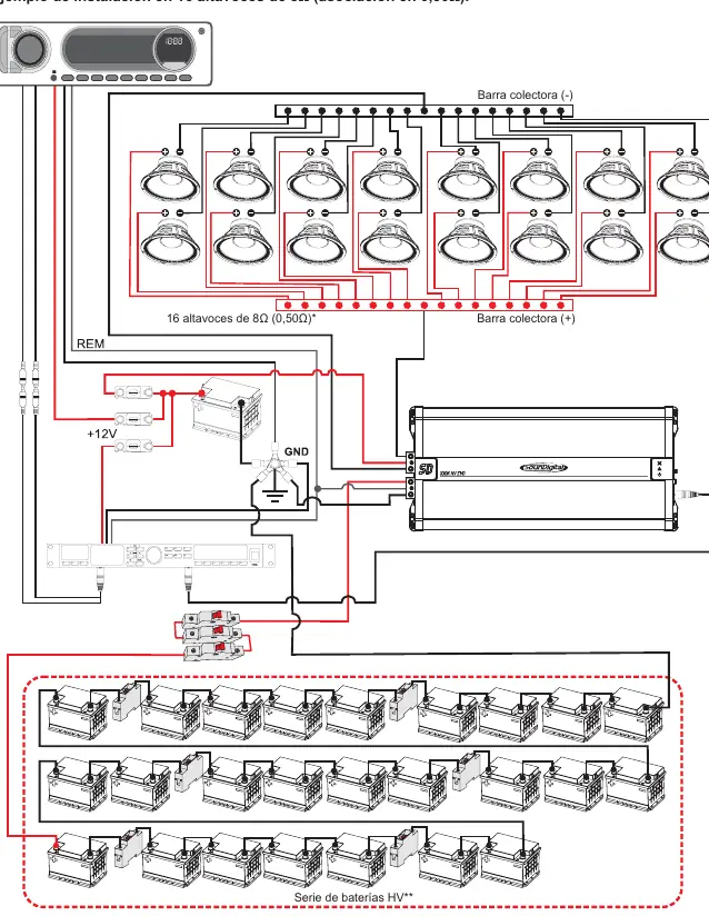
- Speaker Wiring: Illustrates connection for 16 speakers in parallel/series configuration.
Model compatibility
- Requires high-voltage battery systems.
- Do not use RCA and XLR inputs simultaneously.

Manual page author
Michael Turner
Technical manual editor
Reviews PDF manuals for structure, safety notes, and practical product details so readers can find the right information quickly.