Power / Transfer Switches
Installation and Operating Guide for Fronius Backup Switch 1P/3P-63A
Quick start guide for the Fronius Backup Switch 1P/3P-63A. Includes installation steps, wiring diagrams, commissioning procedures, and configuration settings for backup power.
Quick answers from the manual
Quick answer
- The Fronius Backup Switch 1P/3P-63A is installed by mounting the unit, connecting power and data cables according to the wiring diagram, and configuring the 'Full Backup' mode in the inverter's user interface. p. 2, 3, 4
Key actions
- Mounting the switch p. 2
- Connecting data communication p. 3
- Configuring Backup Power p. 4
First start
- Ensure the system is powered off, perform wiring, install protective cover, and configure via inverter UI. p. 2, 3, 4
Technical specifications
| Parameter | Value | Meaning | Pages |
|---|---|---|---|
| Power Terminal Torque | 3 Nm | Required torque for power connections | p. 2, 3 |
| Protective Cover Torque | 0.2 Nm | Required torque for cover screws | p. 3 |
Where to find it in the PDF
- Safety and Mounting p. 2
- Wiring and Commissioning p. 3
- Configuration and Testing p. 4
Table of contents
Manual images
Click an image to enlargeQuick guide from the manual
This document provides essential installation, wiring, and configuration instructions for the Fronius Backup Switch 1P/3P-63A. Installation and commissioning must be performed by trained personnel in accordance with national standards. Ensure all documentation is read and understood before beginning work.
Mounting and Installation
The device must be mounted securely. Follow these steps for preparation and installation:
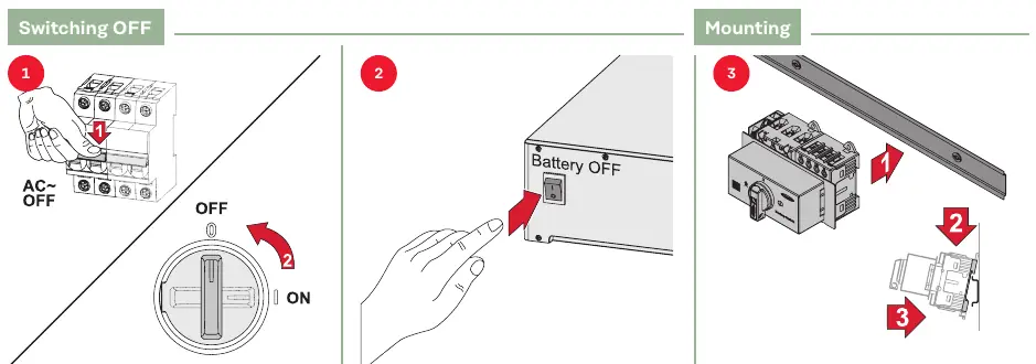
- Switching OFF: Ensure the system is powered off before starting installation.
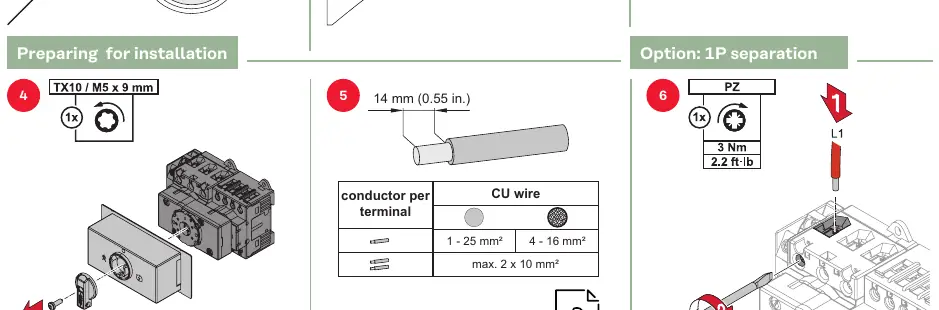
- Preparation: Strip wires to the specified lengths: 14 mm for power terminals and 8 mm for data communication.
- Power Terminals: Use a torque of 3 Nm (2.2 ft-lb) for power connections.
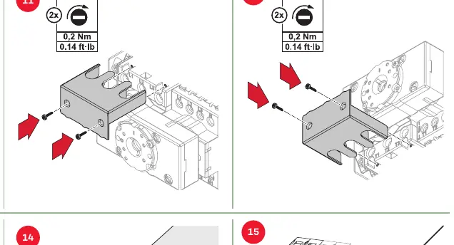
- Protective Cover: Install the protective cover using a torque of 0.2 Nm (0.14 ft-lb).
Wiring and Connections
The backup switch requires connection to the inverter and smart meter for data communication. Ensure correct wire sizing:
- Power wires: 1 - 25 mm² (CU wire).
- Data communication wires: 0.13 - 2.5 mm² (CU wire).
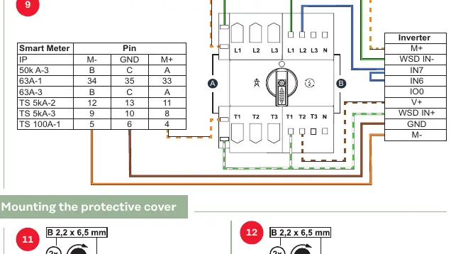
- Refer to the wiring diagram in the manual for specific pin assignments between the Smart Meter and the Inverter (M+, GND, M-).
Commissioning and Configuration
After physical installation, configure the system via the inverter's user interface:

- Open the user interface of the inverter.
- Navigate to Device Configuration > Functions and I/Os.
- Activate Backup Power.
- Select Full Backup under the Backup Power Mode settings.
Testing
Once configured, test the backup power function to ensure the switch correctly transitions between grid supply and backup power supply modes.
Manufacturer information
Fronius International GmbH
Practical help
Common problems
Incorrect operation or poorly executed work
Ensure installation is performed by trained personnel and all safety documentation is read and understood.
PV modules generating voltage
Be aware that PV modules exposed to light supply voltage to the inverter; take appropriate safety precautions.
Before use
- Verify installation is performed by trained personnel
- Read all provided hard copy and online documentation
- Ensure the system is switched OFF before starting
- Check wire stripping lengths (14 mm for power, 8 mm for data)
- Verify torque settings (3 Nm for power, 0.2 Nm for cover)
Specs in practice
- Power Terminal Torque
- 3 Nm (2.2 ft-lb) required for secure power connections.
- Protective Cover Torque
- 0.2 Nm (0.14 ft-lb) required for the protective cover screws.
- Power Wire Size
- 1 - 25 mm² for power terminals.
- Data Wire Size
- 0.13 - 2.5 mm² for data communication.
Images and diagrams
- Wiring diagram shows connections between Smart Meter and Inverter (M+, GND, M-).
- Mounting steps illustrate the physical installation of the switch.
- User interface configuration steps guide through the inverter settings menu.
Model compatibility
- Compatible with 1P and 3P systems.
- Requires specific inverter configuration for Backup Power mode.

Manual page author
Michael Turner
Technical manual editor
Reviews PDF manuals for structure, safety notes, and practical product details so readers can find the right information quickly.