Power / Batteries & Chargers
User Manual for Fronius Smart Meter TS 100A-1
Quick start guide for the Fronius Smart Meter TS 100A-1. Includes technical specifications, installation steps, wiring diagrams, and configuration settings for the device.
Table of contents
Manual images
Click an image to enlargeQuick guide from the manual
This document provides the essential steps for installing and commissioning the Fronius Smart Meter TS 100A-1. The device is designed for measuring energy consumption and requires professional installation. Ensure you have read all safety documentation before beginning.
Safety Information
Warning: Incorrect operation or installation can cause serious personal injury or material damage. The device must only be installed and commissioned by trained personnel within the scope of technical regulations.
Technical Specifications
- Nominal Voltage: 230 V (-30 % to +20 %)
- Nominal Current: 5 A (Maximum 100 A)
- Frequency: 50 - 60 Hz
- Communication: RS485 (9600 or 19200 bit/s)
- Mounting: 35 mm DIN rail
- Protection: IP51 (housing), IP20 (connections)
- Operating Temperature: -25 to +65 °C
Installation and Wiring
- Power Off: Switch off the circuit breaker before starting.
- Mounting: Snap the Smart Meter onto a 35 mm DIN rail.
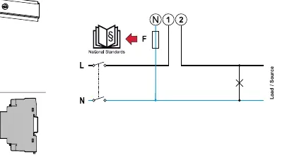
- Wiring: Connect the L and N lines according to the 1-phase wiring diagram.
- Protective Cover: Install the protective cover over the terminals.
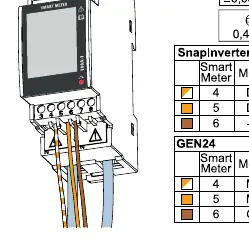
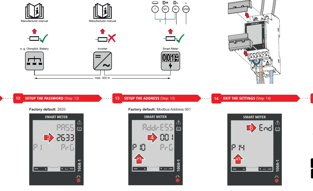
- Data Cables: Connect the RS485 data cables (D+, D-, GND).
- Terminating Resistor: If required, set up the terminating resistor between T and M- terminals.
- Connector Covers: Install the connector covers.
- Power On: Switch the circuit breaker back on.
Configuration and Settings
After installation, navigate the settings menu using the buttons on the device:
- Navigate: Use page up/down buttons.
- Confirm: Hold the adjust/confirm button for 2 seconds.
- Password: The factory default password is 2633.
- Address: The factory default Modbus address is 001.
- Commissioning: Use the Fronius Solar.start app to finalize the system setup.
Official resources from the manual
Manufacturer information
Fronius International GmbH
Practical help
Common problems
Device not communicating with inverter
Check RS485 wiring (D+, D-, GND) and ensure the terminating resistor is correctly installed if required.
Cannot access settings menu
Ensure you are using the correct factory default password: 2633.
Incorrect energy readings
Verify that the phase (L) and neutral (N) wires are connected to the correct terminals and that the current transformer orientation is correct.
Before use
- Ensure the main circuit breaker is switched off.
- Verify the DIN rail is 35mm.
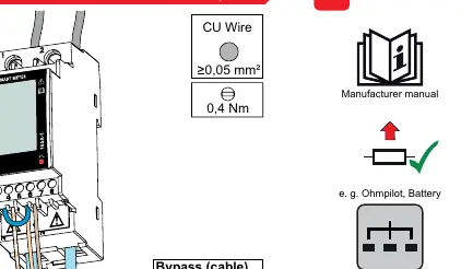
- Check that wire cross-section is within limits (max 25mm² for measuring input).
- Have the Fronius Solar.start app installed on your mobile device.
- Ensure you have the necessary credentials for the Fronius system.
Specs in practice
- Nominal Voltage
- The device operates on a 230V single-phase system with a tolerance of -30% to +20%.
- Maximum Current (Imax)
- The meter can handle a maximum current of 100A.
- RS485 Communication
- Used for data transmission to the inverter; supports 9600 or 19200 bit/s.
Images and diagrams
- The wiring diagram illustrates the connection of L and N lines to the Smart Meter.
- The terminating resistor setup requires a connection between terminals T and M-.
Model compatibility
- Requires Fronius Datamanager 2.0 (version 3.16.1 or higher).
- Requires Fronius Symo Hybrid (version 1.16.1 or higher).

Manual page author
David Miller
Documentation analyst
Organizes user manual content into clear summaries, with attention to model details, product context, and everyday usability.