Power / Batteries & Chargers
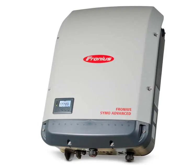
User Manual for Fronius Symo Advanced Solar Inverter
Quick start guide and installation manual for the Fronius Symo Advanced solar inverter. Includes mounting instructions, AC/DC wiring diagrams, commissioning steps, and safety guidelines.
Table of contents
Manual images
Click an image to enlargeQuick guide from the manual
This document provides essential instructions for the installation and commissioning of the Fronius Symo Advanced solar inverter. Important: Installation must be performed by trained personnel. Before starting, ensure you have read all provided documentation. PV modules exposed to light generate voltage, so exercise caution during wiring.
Safety information
- Electricity Hazard: PV modules supply voltage to the inverter when exposed to light.
- Hot Surface: Components may become hot during operation.
- Qualified Personnel: Only trained professionals should install and commission the device.
- Compliance: Ensure all local technical regulations are followed.
Mounting conditions
The inverter is designed for specific environmental conditions:
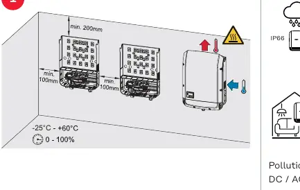
- Protection Rating: IP66 (dust-tight and protected against powerful water jets).
- Temperature Range: -25°C to +60°C.
- Clearances: Maintain minimum clearances of 100mm on sides and 200mm above/below the unit.
- Altitude: Suitable for use up to 4000m (derating applies above 3400m).
- Pollution Degree: 2.
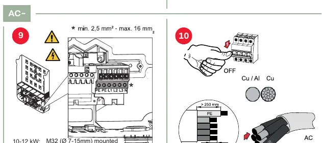
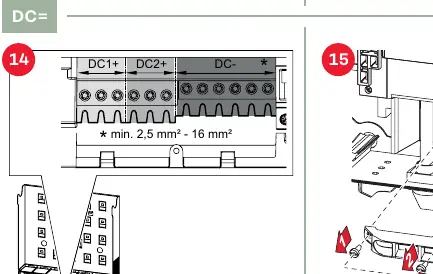
Installation and wiring
Follow these steps for physical installation:
- Opening: Remove the cover using the provided screws (4x TX25).
- Mounting: Secure the mounting bracket to the wall. Ensure the surface can support the weight.
- AC Wiring: Connect the AC cables (PE, L1, L2, L3, N). Ensure correct cross-sections (min 2.5mm²).
- DC Wiring: Connect DC+ and DC- strings. Ensure correct polarity. Use appropriate cable cross-sections (min 2.5mm² - 16mm²).
Inverter commissioning
Once installed, follow these steps to start the system:
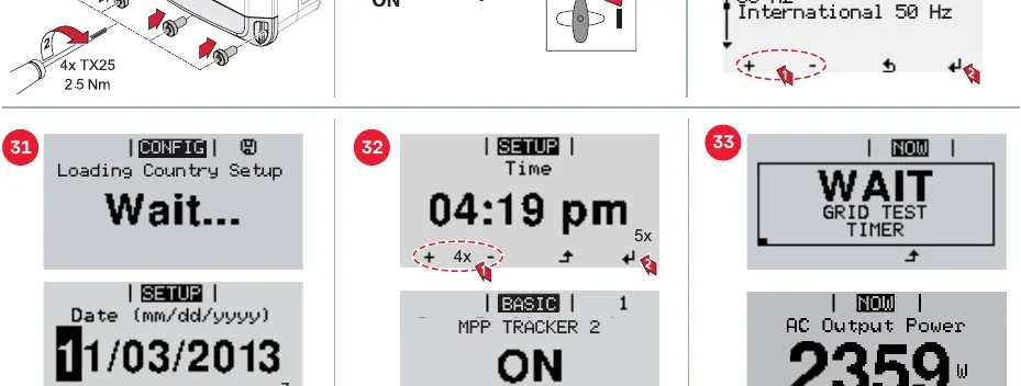
- Ensure all wiring is secure and the cover is closed.
- Switch on the AC power.
- The display will guide you through the initial setup.
- Select the appropriate country setting (e.g., International 50 Hz).
- Set the date and time.
- The inverter will perform a grid test and then begin operation.
Firmware and software updates
Updates can be performed via the USB port on the inverter. Insert a USB drive with the update file and navigate to the Setup menu on the display to initiate the Software Update process.
Manufacturer information
Fronius International GmbH
Practical help
Common problems
Inverter not starting
Ensure PV modules are exposed to light and providing sufficient voltage. Check that all DC connections are secure.
Wiring errors
Verify that AC and DC cables are connected to the correct terminals (PE, L1, L2, L3, N for AC; DC+ and DC- for DC) and that cross-sections meet the minimum requirements.
Setup/Configuration issues
Ensure the correct country setting is selected during the initial commissioning phase on the display.
Before use
- Read all provided documentation (hard copy and online).
- Ensure installation is performed by trained personnel.
- Verify the mounting surface can support the weight of the inverter.
- Check that environmental conditions (temperature, altitude) are within specifications.
- Ensure PV modules are not exposed to light during the wiring process.
- Verify that the AC grid connection meets local standards.
Specs in practice
- Pollution degree 2
- The environment should only have non-conductive pollution.
- WLAN Frequency
- Operates on channel 1-11 (2412-2462 MHz) with <100 mW power.
Images and diagrams
- Mounting: Maintain minimum clearances of 100mm (sides) and 200mm (top/bottom) for proper ventilation.
- AC Wiring: Connect PE, L1, L2, L3, N according to the terminal markings.
- DC Wiring: Ensure DC+ and DC- strings are connected with correct polarity.
Model compatibility
- Requires a Type A RCD (Residual Current Device) with IΔN ≥ 100 mA.
- Compatible with PV systems within the specified voltage ranges (up to 1000V depending on altitude).

Manual page author
David Miller
Documentation analyst
Organizes user manual content into clear summaries, with attention to model details, product context, and everyday usability.