Power / Transfer Switches
Quick Start Guide for Fronius Backup Switch 1P/3P-63A
Quick start guide for the Fronius Backup Switch 1P/3P-63A. Includes installation, wiring diagrams for power and data, configuration steps, and safety instructions.
Quick answers from the manual
Quick answer
- The Fronius Backup Switch 1P/3P-63A is an electrical switch for PV systems. This guide covers installation, wiring (power and data), and configuration for backup power functionality. p. 1, 4, 7
Key actions
- Mounting the switch p. 4
- Wiring power p. 4, 5
- Configuring inverter p. 7
First start
- Ensure all connections are secure, mount the protective cover, switch on the battery, and activate the switch. p. 6
Technical specifications
| Parameter | Value | Meaning | Pages |
|---|---|---|---|
| Power terminal torque | 3 Nm | Tightening torque for power cables | p. 4 |
Where to find it in the PDF
- Safety Warnings p. 2, 3
- Installation and Wiring p. 4, 5, 6
- Configuration p. 7
Table of contents
Manual images
Click an image to enlargeQuick guide from the manual
This document provides essential installation and configuration instructions for the Fronius Backup Switch 1P/3P-63A. It is intended for trained personnel only. Before starting, ensure all power sources are disconnected and you have read all provided documentation.

Safety Information
Warning: Incorrect operation or poorly executed work can cause serious injury or damage. Installation and commissioning must be carried out by trained personnel in accordance with national standards. PV modules exposed to light supply voltage to the inverter; treat all components as live.
Installation and Mounting
The device is designed for mounting on a standard DIN rail.
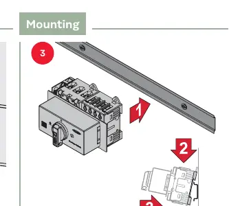
- Ensure the switch is in the OFF position.
- Mount the device securely onto the DIN rail.
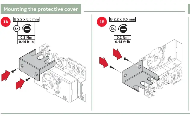
- Install the protective cover after wiring is complete to prevent accidental contact.
Power Wiring
Follow the specific wiring diagrams for 1P or 3P separation based on your system configuration.
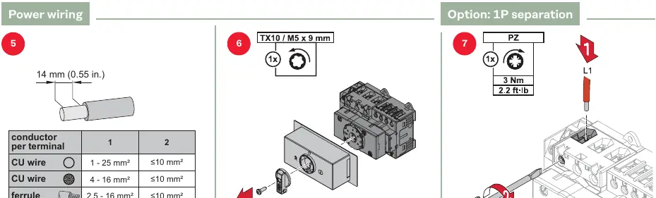
- Stripping length: 14 mm.
- Torque: 3 Nm for power terminals.
- Ensure wire cross-sections match the specifications provided in the manual (e.g., 1-25 mm² for CU wire).
Data Wiring
The device supports Modbus RTU and Modbus TCP/IP | MQTT configurations.
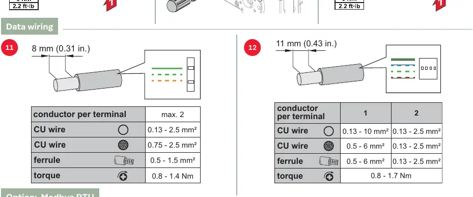
- Stripping length: 8-11 mm.
- Torque: 0.8 - 1.7 Nm for data terminals.
- Follow the pinout diagrams provided for the Smart Meter and Inverter connections.
Commissioning and Configuration
Once installed and wired:
- Switch on the battery.
- Perform the commissioning steps to secure the protective cover.
- Switch the device to the ON position.
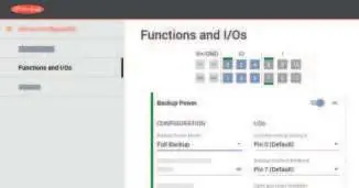
- Access the inverter user interface.
- Navigate to Device Configuration > Functions and I/Os.
- Activate Backup Power.
- Select Full Backup under Backup Power Mode.
Testing
Verify the backup power function by testing the switch positions (Grid supply, OFF, Backup power supply) to ensure the system behaves as expected.
Manufacturer information
Fronius International GmbH
Practical help
Common problems
Backup power not activating
Ensure 'Full Backup' is selected in the inverter's 'Backup Power Mode' settings and that the switch is in the correct position.
Before use
- Ensure installation is performed by trained personnel.
- Verify all power sources are switched off before starting.
- Check wire cross-sections against terminal specifications.
- Ensure correct torque settings are applied to all terminals.
- Verify the protective cover is installed before commissioning.
Specs in practice
- Power Terminal Torque
- 3 Nm is required for secure power cable connection.
- Data Terminal Torque
- 0.8 - 1.7 Nm is required for data cable connection.
- Power Wire Stripping
- 14 mm of insulation must be removed.
Images and diagrams
- Wiring diagrams illustrate connections between the Smart Meter, Inverter, and Grid.
- Mounting steps show the sequence for DIN rail installation.
- The user interface diagram highlights the path to enable Backup Power settings.
Model compatibility
- Compatible with 1P and 3P systems.
- Requires specific inverter configuration via the user interface.

Manual page author
David Miller
Documentation analyst
Organizes user manual content into clear summaries, with attention to model details, product context, and everyday usability.