Power / Transfer Switches
User Guide for Fronius 1PN/3PN-63A Backup Switch
Quick start guide for the Fronius 1PN/3PN-63A Backup Switch. Includes installation, wiring diagrams, data communication setup, and inverter configuration steps.
Quick answers from the manual
Quick answer
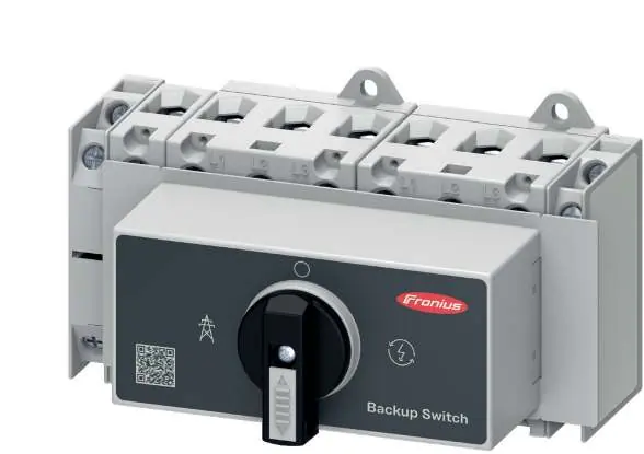
- The Fronius 1PN/3PN-63A Backup Switch is a device for managing backup power in solar systems. Installation requires trained personnel, proper wiring of power and data lines, and configuration of the 'Full Backup' mode in the inverter's user interface. p. 1, 2, 3, 4
Key actions
- Mounting the switch p. 2
- Wiring power p. 2, 3
- Configuring inverter p. 4
First start
- Ensure all wiring is secure, mount the protective cover, and configure 'Full Backup' mode in the inverter's Device Configuration menu. p. 3, 4
Technical specifications
| Parameter | Value | Meaning | Pages |
|---|---|---|---|
| Power terminal torque | 3 Nm | Tightening torque for power connections | p. 2, 3 |
| Protective cover torque | 0.2 Nm | Tightening torque for cover screws | p. 3 |
Where to find it in the PDF
- Safety and Mounting p. 2
- Wiring and Commissioning p. 3
- Configuration p. 4
Table of contents
Manual images
Click an image to enlargeQuick guide from the manual
This document provides installation and configuration instructions for the Fronius 1PN/3PN-63A Backup Switch. It is intended for trained personnel only. Ensure all safety documents are read and understood before beginning installation. The device manages backup power in solar systems and requires specific wiring and inverter configuration.
Safety information
- Installation and commissioning must be carried out by trained personnel in accordance with national standards.
- PV modules exposed to light supply voltage to the inverter; exercise extreme caution.
- Ensure all printed and online documentation is read and understood.
Installation and mounting
The device is designed for DIN rail mounting. Ensure the system is switched off before starting installation.
- Switching OFF: Ensure the AC supply is off and the device is in the OFF position.
- Mounting: Secure the device onto the mounting rail.
- Preparing for installation: Strip wires to 14 mm. Use appropriate wire cross-sections: 1-25 mm² or 4-16 mm² for power terminals.
Wiring and data communication
Follow the specific wiring diagrams provided for your system type (1PN or 3PN separation).
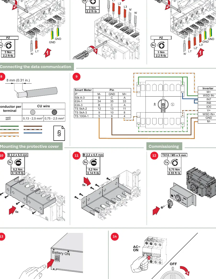
- Power connections: Tighten power terminals to 3 Nm (2.2 ft-lb).
- Data communication: Connect the data cable (0.13 - 2.5 mm² or 0.75 - 2.5 mm²) according to the pinout table provided in the manual, connecting the Smart Meter pins to the Inverter pins.
- Protective cover: Mount the protective cover using the provided screws, tightening to 0.2 Nm (0.14 ft-lb).
Commissioning and configuration
After physical installation, configure the inverter software:
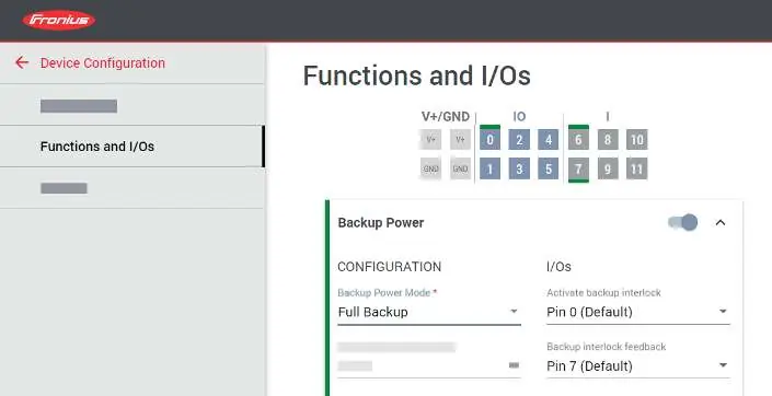
- Open the user interface of the inverter.
- Navigate to Device Configuration > Functions and I/Os.
- Activate Backup Power.
- Select Full Backup under Backup Power Mode.
Test the backup power function by switching the device to the backup power supply position to verify operation.
Manufacturer information
Fronius International GmbH
Practical help
Common problems
Inverter not detecting backup power
Verify that the data communication wiring matches the pinout table and that 'Full Backup' mode is correctly selected in the inverter settings.
Before use
- Ensure installation is performed by trained personnel.
- Verify PV modules are not exposed to light or handle with extreme caution.
- Check wire cross-sections (1-25 mm² or 4-16 mm²).
- Ensure correct torque settings (3 Nm for power, 0.2 Nm for cover).
- Confirm the system is switched off before starting.
Specs in practice
- Power terminal torque
- 3 Nm (2.2 ft-lb) tightening torque for power connections.
- Protective cover torque
- 0.2 Nm (0.14 ft-lb) tightening torque for cover screws.
- Data cable cross-section
- 0.13 - 2.5 mm² or 0.75 - 2.5 mm² depending on wire type.
Images and diagrams
- Wiring diagrams for 1PN and 3PN separation are provided to guide power connections.
- Data communication table maps Smart Meter pins to Inverter pins.
Model compatibility
- Designed for use with Fronius inverters.
- Requires specific inverter configuration via the user interface.

Manual page author
Emily Carter
User documentation editor
Prepares concise manual descriptions and highlights the most useful setup, operation, and maintenance information for readers.